


72linerlover
-
Posts
81 -
Joined
-
Last visited
Content Type
Events
Profiles
Forums
Media Demo
Everything posted by 72linerlover
-
 Hi, Tony. I found out an old book that is a translation of a french one. Jean Bouillier says that he personally mesured the diameter of the pax windows in the Museum of Le Bourget (F-BAZR). Real thing diameter 365mm; 1/72 scale 5,1mm. link Hope this helps. Best regards. Eugenio
 -
Hi Tomas. That's fun. I was going to post the same link. Considaration: before struggle with scribing, take a look to some photos and try to find really visible pannel lines on an Airbus. Than make your choice. Best regards Eugenio
-
Making a DC-7C from Heller's DC-6 (1:72 scale)
72linerlover replied to tomprobert's topic in Work in Progress - Aircraft
Hi, Tom. A'm always happy to see a 7C in the works. Good progress Unfortunatelly Heller made a mistake in the istruction sheet (and in the moulds) indicating to glue the air conditioner inlett on the left side of the fuselage. It seems to me from your third pic of your post that you did that way. At this stage, you still are on time to put it on the right side. Lots of images on the web Check also in this thread, there are some interesting drawings. Keeep up the good work. Best regards Eugenio- 25 replies
-
- 1
-

-
- AIM
- Transport Wings
- (and 1 more)
-
Fieseler Fi156 ‘Storch’ Heller - WIP
72linerlover replied to Giampiero Piva's topic in Work in Progress - Aircraft
Dear Giampiero, it's nice to see your signature here. Let me be the first to compliment with you. I think that our learning curve will rise quickly, following your builds. Have a nice day. Eugenio -
Hi Paul. Not sure about the painting, so I let other experts explain. I just wanted to bring your attention on the position of the air conditioner inlet, under the belly. The Heller instruction tell to glue it on the left side, but this is wrong: just place it on the riglt side. See this pic. Good luck with your build. Eugenio
-
Bell 206 Jet Ranger - canopy shape?
72linerlover replied to bootneck's topic in Modern - 1969 and onwards
Hi, Mike. I think your diagram is right. Look here. If you look closely along the central frame, specialy on top of it, you'll notice the kink. Click on the "Enlarge Image" below the pic. I had that impression seeing a 206 live some years ago, but didn't ivestigate. That's a big challenge for a modeler! Best regards Eugenio -
Upgrade article for the Airfix F-27 kit.
72linerlover replied to Admiral Puff's topic in Classic - up to 1968
Hi Admiral. Could this be what you're looking for? https://designer.home.xs4all.nl/models/f27/f27mod.htm Bye Eugenio -
Turbofan fan blurs, how?
72linerlover replied to busnproplinerfan's topic in Modern - 1969 and onwards
Hi, there. Do you mean something like that? The images are mine and royalty free. Bye Eugenio- 15 replies
-
- 1
-
-
- jet engine blades blur
- fan blur
- (and 1 more)
-
Lynx HAS-3 ICE - Hobby Boss 1/72
72linerlover replied to phantom61's topic in Work in Progress - Aircraft
Oh, come on, Silvano: be serious. I've nothing to teach you, nor I had. Ciao- 96 replies
-
- 1
-
-
- 1:72
- Hobby-Boss
- (and 1 more)
-
Lynx HAS-3 ICE - Hobby Boss 1/72
72linerlover replied to phantom61's topic in Work in Progress - Aircraft
Silvano, this time you've gone beyond yourself. Well, difficult to tell which of your models is the best, but i'm quite sure to say that this one is a step forward the others. Congrats Eugenio- 96 replies
-
- 2
-
-
- 1:72
- Hobby-Boss
- (and 1 more)
-
Hi, Lord Riot. It is nice to see a "Seven Seas" coming along. I have investigated this Old Lady when I built one in 1/72nd scale. I have noticed that in the Roden kit, both ailerons have three trim tabs. Actually the left one has, but the right one only two. It is just a little correction with some putty. In the following pic you notice the difference. Keep the nice work up. Best regards Eugenio.
- 21 replies
-
- 6
-
-

-
- 1/144
- Classic airliner
- (and 1 more)
-
Lynx HAS-3 ICE - Hobby Boss 1/72
72linerlover replied to phantom61's topic in Work in Progress - Aircraft
The answer is here. Bye- 96 replies
-
- 2
-

-
- 1:72
- Hobby-Boss
- (and 1 more)
-
Lynx HAS-3 ICE - Hobby Boss 1/72
72linerlover replied to phantom61's topic in Work in Progress - Aircraft
Wow! The Fox and the Cat at work together. A single plan that works is better than a hundred doubtful plans. (Rohini Chowdhury) Top modeling in northern Italy. Happy Phase 2. Eugenio- 96 replies
-
- 3
-
-
- 1:72
- Hobby-Boss
- (and 1 more)
-
Lynx HAS-3 ICE - Hobby Boss 1/72
72linerlover replied to phantom61's topic in Work in Progress - Aircraft
Hi, Silvano. Beautiful job. So another time you're fighting with something that has propellers, or at least something rotating outside the airframe. When I first saw that big stick in the rotor shaft place, I thought you were going to put it on a barbecue. Just kidding. You're really making a masterpiece! Who would expect something different? Ciao Stay healthy - stay home Eugenio- 96 replies
-
- 2
-
-
-
- 1:72
- Hobby-Boss
- (and 1 more)
-
It's fast! It's British! It's a Lightning!
72linerlover replied to giemme's topic in Work in Progress - Aircraft
Hi, Giorgio. Glad that you're doing well. When we had a phone call middle march, I felt you weren't in your usual spirit, so I suspected... but the Corona was away from you. Well, now it's over, but take the maximum care of you so that your temporary weakness doesn't compromise things. Eugenio- 693 replies
-
- 1
-
-
- 111 Squadron
- EE Lightning
- (and 1 more)
-
Hi, Buzz. Since your question has already more than 70 views and no answer, I' try to share my thoughts. For me it is impossible to print in white, at least in home printing. There are some producers as parkes682 decals https://www.britmodeller.com/forums/index.php?/forum/131-parkes682decals/ that perhaps is useful to contact. But, if you are in the know of the exact rgb or cmyk code of the blue, I would go for a sort of "negative printing": it is possible to print a blue rectangle on a transparent decal paper and letting the lettering clear. If you shoot the white on the area, you will place there the said rectangle. It would also be possible to cut the rectangle to the size and shape of a panel in order to get a more realistic effect. If you want, you can contact me directly for the size of the lettering and I'll do my best to rebuild the font with CAD (since if we cannot speak of a real font in that era). Of course, that is for free. Cheers Eugenio
-
Ok, ianwau. I need some time to organize information in a decent way. Sadly me too, because the items are interesting, but awfully done, at least at the cost they require. Regards Eugenio
-
Hi, ianwau. I discovered your thread some days ago, but I find time to replay only now. First of all: congratulation for your approach to this difficult build. I have in the stash the same kit since 2014 that a friend of mine brought me directly form France. I wrote some notes about the surgery needed in order to get a decent model and the last sentence was: "I don't see any alternative to build a new wing and adapt the engines nacelles on". And to make new wings I thought to a wooden core with thin plasticard glued on. Unfortunately the airfoil (and the consequent wing/body fairing) is not the only problem. If you need, I can post some references about the other issues and the correction needed as the level of the pax windows that should be at least 2 mm lower. etc.... Good luck for you build. Regards Eugenio
-
Correcting the 1/72 Super Constellation
72linerlover replied to Gooney Fan's topic in Classic - up to 1968
Hi, Gooney Fan. Unfortunately I missed to buy a correction set for the Superconstellation too. Of course my hope is that Paul will be able to resume production, more for him than for me. Anyway the site is still up, except for the shopping cart. At this link you can find three images of the tip tanks. They are so nice that you can use as reference for scratcbuilding them. As you see, the most evident difference is in the lenght, so that the correct tank results more slim. (I can guess the diameter is almost correct) At this other link there is a quite reliable drawing that can give you an idea. Hope this helps. Best regards Eugenio -
A pair of Airfix Hawks in 1/72. Finished.
72linerlover replied to Fritag's topic in Work in Progress - Aircraft
Hi, Steve. Glad that the Mr. Surfacer worked on the grills. Stellar job on those details. I've just found something about the pylons. Not sure, though, if pertinent with your specific aircraft type. Link1 Link2 Link3 Link4 Le last one leads you to a thread of RC models. Just scroll down almost at the end of the page, look at image on the right. Best regards Eugenio -
A pair of Airfix Hawks in 1/72. Finished.
72linerlover replied to Fritag's topic in Work in Progress - Aircraft
Hi Steve. In case of so small stuff, I use some enamel paint or Mr. Surfacer. Just let evaporate a while before applying. Always following with great interest your progress. Regards Eugenio -
A pair of Airfix Hawks in 1/72. Finished.
72linerlover replied to Fritag's topic in Work in Progress - Aircraft
Hi, Fritag. For my resin masters I used a cheap "Prochima" 1:1 resin and I was simply lucky waiting only two or three days. Never done before, but perhaps a gentle buffing with a rubbing alcohol dumped cloth could help. Or simply with water and soap. About the final thickness after forming, I'll tell you that I use plunge forming, without vacuum and hold the clear plastic by two side clamps. This way you get an almost constant thickness. Ok, not very scientific or industrial, but I'm happy with that. I seem to remember to have done this way working with Silvano anh his Chipmunk too. Cheers Eugenio -
A pair of Airfix Hawks in 1/72. Finished.
72linerlover replied to Fritag's topic in Work in Progress - Aircraft
Hi, Fritag, welcome back from me too. I remember exactly what you did for the Chipmunk canopy. Don't worry about the withstand of the resin under the heat solicitation during thermoforming, if the master is really totally catalysed. If you noticed in the past some effect on the clear plastic, it was probably due to some release of the "polyol" of the resin that did not truly mix with the catalyzer. So let the master set for a pair of days, be gentle with plastic heating and quick in forming. Make sure you put (glue) the master on a flat surface only some millimeter narrower as its contour. I mean something like this, even if here the master is in one piece with the support. This is important because, if you keep the master on top of a little rod, you may run the risk to bend it during thermoforming. Hope this helps. Bye Eugenio -
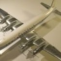
Good morning. The 707 family is probably one of the most complicated among airliners. Let's make it clear. Our friend has two 1/72 707, so 1/144 is out of discussion. The Heller kit is a long body one, a -300B series. With the introduction of RR engines, -400 means RR engines, so -430 is the RR Long body, but only corresponding to the 320 with Pratt&Witney JT-4A. Please note: only 320 and not -320B or -320C. Lufthansa had four 707-430 ( D-ABOG, D-ABOC, D-ABOD, D-ABOF) BOAC had ten 707-430, actually designated 707-436 (G-APFF, G-APFH, G-APFI, G-APFJ, G-APFK, G-APFL, G-APFM, G-APFN, G-APFO, G-APFP) Both Lunthansa and BOAC operated -300B and 300C (cargo) series, with Pratt&Witney JT-3D engines. Their designation was BOAC 707-336B/C, Lufthansa 707-330B/C, but this is another story. Now back to modelling, the wing plantform at the root of the -430 is closer, except for the dimensions, to the -120 (short body) series, but not impossible to achive from the -300B wing, if the Ha Hen instruction (that I don't know them) are correct. You'll also need to rescribe a very short section of the split flaps under the fillet at the root. I see a big challenge in rebuild the wing-to-body fairing, that, obviously is closer to the short body one and involves both the wing and the fuselage modifications. As a side note, just speaking of "side": unfortunately Heller misaligned the cockpit with the passengers' cabin windows. So, in a side view of the fuselage, you should see an ideal line running through the bottom of the pax windows hitting the lower end of the first frame of the cockpit. Take a look on the pics on the net and you'll get the point. The liveries of that time are merciless with misalignments. Sorry if I have been tedious, but I wanted to share with you the information I collected and hope they are right. Good luck, Tommo, with your build. Best regards. Eugenio
-
Hi, Neil.
I don't wanted to write this in the thread, but I am afraid that there is a wrong picture in your post of last Sunday (#57).
The first image refers to the DC-7B and there is quite visible the central plug for the wing extension. As far as I know it is only for the DC-7C. This could be misleading.
Congratulations on your project from a modeler that knows how challenging is to convert a 6B into a 7C.
Regards
Eugenio