


Nigel Heath
-
Posts
8,773 -
Joined
-
Last visited
-
Days Won
62
Content Type
Events
Profiles
Forums
Media Demo
Posts posted by Nigel Heath
-
-
Cracking work on the decals, it really does look the part.
-
 1
1
-
-
Good point about all the wiring and plumbing. I think most of it has to be added after painting as it's typically a different colour from the general grey of the interior but some preparation such as drilling of holes needs to be done before then.
-
1
-
-
Looks great with the decals on. Thanks for all the feedback on the shortcomings of the Print Scale decals, duly noted and I will hopefully avoid the worst of the pitfalls when I get to using mine. And I got you onto page 3.
-
1
-
-
Modelling wise today has been entirely concerned with winch construction. I did however add a bit more detail to the bulkhead last night as well as trimming out a blank for the winch frame:

With tin snips and a sanding stick that was shaped like so:
Then folded to shape on my bending tool:
Next I made a start on the winch drum using a length of plastic tube and a 2.5mm punched out disc of card:
With the other send capped off with another disc I then wrapped it with some tinned copper wire to represent the cable:
Next I made a couple of shaped side pieces from some 0.4mm card based mainly on this reference picture:
With those added I glued in the drum and added the whole assembly to the bulkhead:
The final part (for now) was to add a 1.6mm disc of card to represent the hub drive:
There a few more parts to add but those are best done after painting I think.
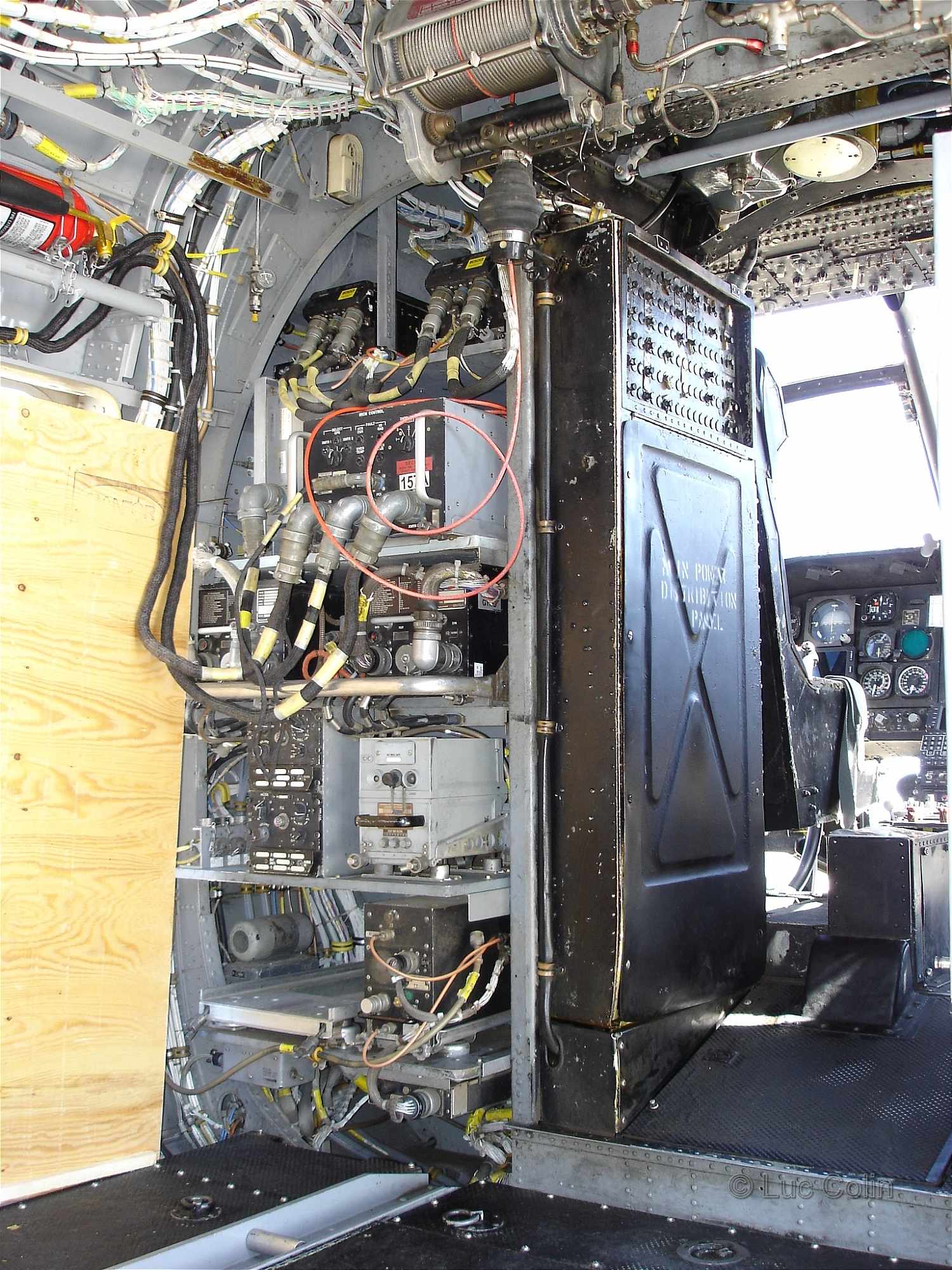
I think the next job will be to add some equipment boxes to the shelves as per this reference photo:
But now I need to get a baked potato in the oven for my dinner.
Bye for now,
Nigel
-
3
-
-
After a dinner of chilli beef and lettuce wraps (from Gordon Ramsay's "Ultimate Cookery Course" recipe book) I have got a bit more done. The next shelf was fabricated much like the first with a combination of 0.5mm brass rod and sheet soldered on the underside with two different melting point solders:
After a bit of clean up and installed it looked like this:
I then made the intermediate shelf out of a scrap of 0.5mm card with a piece of 0.5mm L brass section on the underside:
Here is that installed:
I have also sorted out the filler above the doorway ready for the new winch.
Next the fourth shelf made out a bit more of scrap 0.5mm card with some 0.5mm strip underneath:
I think there are two more shelves to add and then I will get on with the winch for which have a few ideas.
I am also pleased to report that after a after a chat with @azureglo aka Anil tonight, he is well on the way to completing the canopy glazing and will hand deliver these to me next Bank Holiday Monday.
If you haven't guessed already I am having a lot of fun on this build - it's completely ridiculous.
Bye for now,
Nigel
-
4
-
-
Hi folks,
I am pleased to report that my new soldering iron bits arrived on Thursday:
I got to work with the chunkiest of these using this set up to attach the front edge of the lower shelf using regular electronic lead free solder (MP circa 210C):
I then completed the soldering of the side of the shelf using 145C melting point solder with my iron dialed down to 75% power level:
To add some detailing to the shelf I used my mitre box to cut off a length of 1 x 1.5mm Albion Alloys C channel:
The base of that was then tinned using 70C melting point cadmium solder and my iron at 50% power:
That was then soldered onto the shelf with this set up:
After some further clean up including a degrease in some cellulose thinners and drilling a 1.2mm hole the completed shelf was added using regular super glue at the back:
As a reminder this is what I was trying to reproduce:
I think the next job will be to get the other shelves made and installed.
Bye for now,
Nigel
-
4
-
-
Thanks Anil, your efforts are much appreciated. I actually looks a lot better than the masking set I bought.
-
1
-
-
Very neat and tidy finish on the exterior, a panel line wash will bring it all together for sure. Nice of the Luftwaffe to leave some RLM 70 paint behind for their ally to use on future projects. They were a forward planning bunch.
QuoteI hope to enhance it a bit with some wire to represent the hydraulic hoses, can't let Nigel do all the detailing on his own can we!
I haven't even really looked at the rotors yet but I would imagine some hydraulic hoses made from some lead wire would be pretty much mandatory. Looking forward to seeing how yours come out.
-
1
-
-
Yes, my poor old iron bit has almost completely corroded through. I got a new set of bits (and PE seat belts) on order last night and should have them by the end of the week.
-
2
-
-
I have a bit more to report before bed time. I made a start on the racking shelves next to the cabin corridor by drilling some 0.5mm holes and then bending some 0.5mm brass rod in situ with round nose pliers:
After a bit more manipulation I had the shelf surround:
I then tried to solder on a thin brass sheet shelf using this setup but heat sink effect was too great for my soldering iron:
I think my iron should easily be able to do this, examining things I have come to the conclusion that my soldering iron bit is worn out, it has thinned down and can't deliver enough heat, and needs replacing. I do poses new bits but like most of my stuff they are in storage so will have to buy some new ones before proceeding with this. I also have to reorder the seatbelts as the supplier I ordered them form has said they don't know when they will be getting more in stock.
Bye for now,
Nigel
-
3
-
-
Quote
I think the rollers would be a step too far
I have come to much the same conclusion, not only would the "ladder rung" features have to be removed but the existing trough is not deep enough and it would be a heck of a job deepen that.
-
2
-
-
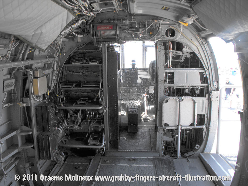
I have made quite good progress today but it started with some destruction. I think this lump at the top of the bulkhead is supposed to be a representation of the winch but it's in the wrong place and will interfere with the retracted upper door so it has to go:
I think I will scratch build a more accurate version and put it in the correct place. As a reminder this is where it should be in relation to the retracted upper door:
After filling the hole left by the winch removal with white Milliput, I turned my attention to the front of the cockpit. First I added the lightening holes thus:
I haven't found any pictures of this area so I'm basically just copying what @milktrip did on his build.
Again pretty much copying what Aaron did, I started on the fabrication of the IP support by making a cardboard template:
A search in one of my scrap boxes located a piece of 0.95mm card that was once going to be the replacement cockpit floor on my Helix build:
Cut out with a combination of scissors and knife action the part was then refined on the model:
That was then turned into the master for the cutting and shaping of the second part.
I needed three internal reinforcement pieces, the end stop on my mitre box is ideal for producing identical multiples like this:
I used 2.5mm square Evergreen strip for the reinforcements but realized they would block some of the lightening holes in the side pieces so cut off some heavy chamfers on the corners and got the first two added like so:
Here is the finished structure:
The final job before bath and dinner time was to fill the ejector marks on the back of the IP, clean up the nasty gate marks and sand off the pips on top of the coaming which I have decided are defects and don't represent anything in reality:
I think the next job with be fabrication the cyclic controls.
Bye for now,
Nigel
-
5
-
-
OK, a little bit more before bedtime, all of the six more tie down rings have been added plus I have started to use my Mission Models 1mm chisel to add the recesses (presumably grab holds for the hinged covers) to the floor:
I used a Tamiya cotton bud and some IPA to remove the worst of the pen and pencil marks. I also reinforced the bonding of the Archer decals with some extra thin super glue - they do not bond well to bare plastic, even when fairly well roughed up as here - I will be hard applying masking tape to them later and really don't want any disasters.
Here with a bit of oblique lighting I think we have the cabin floor more or less finished:
However, those roller tracks have been preying on my mind, they look nothing like the real thing. I will look into replacing them with some dinky aluminium rollers - it may not worth the trip but it will be considered.
Bye for now,
Nigel
-
4
-
-
I have to say I tend to favour matt finishes on models, high gloss finishes can make a model look too toy like. That would give you the opportunity for some weathering which always adds interest to a model. If you want to go down the gloss finish route I would use a semi-gloss for scale effect.
-
2
-
-
Here is a bit more progress on the cabin floor, all of the ring pulls are now installed:
For the tie down rings I first annealed a length of 0.3mm brass rod and then wrapped it round a 0.6mm drill:
Trimmed to size I then soldered the ring using this set up:
For the floor compartment hinges my plan was to use these Archer raised panel lines so a length was extracted:
I have had those decals for quite a few years and it is nice to get some use out of them.
Here are the two hinges in place along with the first tie down ring:
I just have to make and fit six more of the tie down rings and I think the floor will finished.
Bye for now,
Nigel
-
5
-
-
I have been having a bit of a think about the cabin seat for this build and know that of course they are quite similar to the seats I made for my Flying Banana build back in 2013 and have excavated the photos to see how I did it, starting first with a little sketch (as ever):
Legs for these made like so:
Bearers made from 0.8mm rod:
Seat legs and bearers ready for assembly:
Bearers and legs soldered together:
Other leg added like so:
Finished sub-assembly:
Two seats made and diagonal braces added:
Starting to make the lead foil covering:
Hmm, this is how I used the Eduard PE seat backs:
Anyway, after a bit of painting I seemed to have ended up with this as a result of my efforts:
That old cutting mat has long since gone to landfill but I think the rest of things are pretty much OK.
The steat still looks good to me, I will make something like them for this build and you know there may be just a bit more improved soldering techniques and technology.
Bye for now,
Nigel
-
7
-
-
I know from personal exposure that Kumar Towers is far more impressive and palatial than the modest Alton variety which is just frankly a hollow shell - although it has to be said that I did grow up but a stone's throw from there so am rather fond of the place - love that model railway. There are definitely far fewer airbrushes and kits to be found there which in my book makes it a far poorer environment. Many thanks on the work on the masks, it is much appreciated, it is not critical but I could do with the canopy back fairly soon. I am much pleased that Minnie liked the blue cheese sables, she it clearly a fan of saltiness.
I have got a bit more done this afternoon, I started by trying to work out how all the floor detailing worked, I thought it would be related to the cabin sidewall ribbing but it seams to a follow a logic all of it's own. For what I am going to henceforward calling the floor "ring pulls" I had an idea that I could use some of the vintage PE from this Reheat Models instrument bezels set of which I have two fairly intact examples:
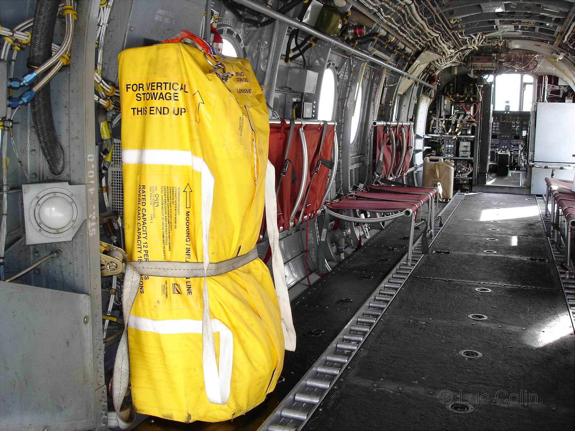
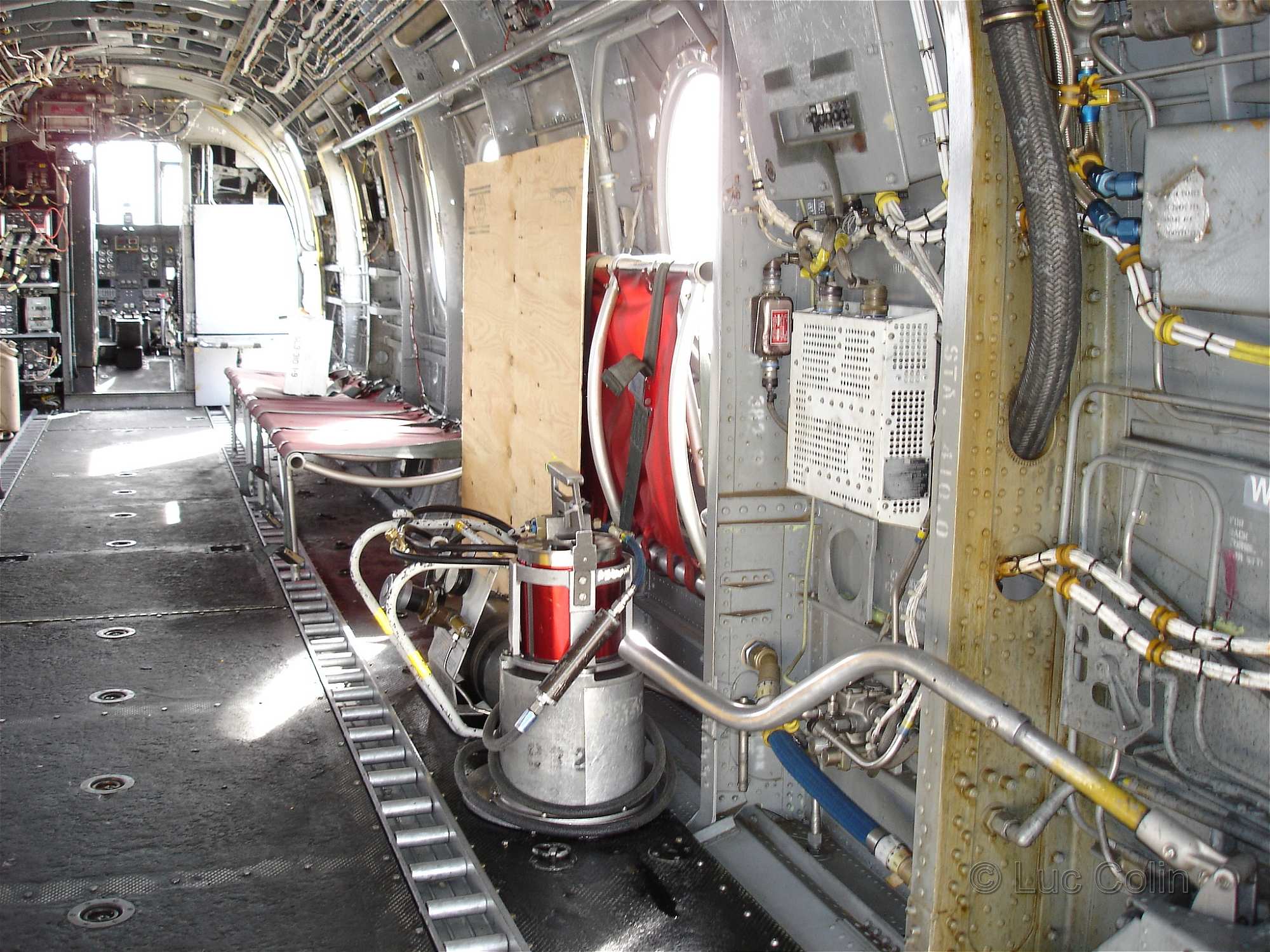
I had probably better show you the main reference photos I have been using for this:
These two old faithfuls were also quite relevant:
I applied two parallel strips of Dymo tape to the floor, mainly as end stops for the scribing but they also proved to be a useful guide for my set square:
I used a 0.5mm drill as a pilot for the ring pull recesses, getting them centered and aligned in the process:
After enlarging the holes with 1.2mm and then finishing with the required 1.5mm drill I was able to deburr the holes and then add the first ring pull to see how things went in the least visible position:
Looks good to me, I will crack on with the rest of them in the morning.
Bye for now,
Nigel
-
4
-
-
Outstanding.
-
1
-
-
Looks great with the decals going on. The masking of the black areas is spot on.
-
1
-
-
That is a lovely looking cockpit, well done.
-
As ever, I am always happy to provide on the catering front. I do get quite good reviews on Trip Advisor for my efforts. I will try to negotiate with Anil on the small tour groups idea, sounds like fun.
-
 2
2
-
-
A visit to Kumar Towers is recommended but it is strictly by invitation only. Free kits and custom masking sets are only available to those on the most inner of sanctums. I suggest a well worded and polite PM to Anil @azureglo might just unlock the key to this magical world.
-
3
-
-
I can provide plenty of reference material if required but a simple Google search of walkarounds should provide most of the information you require. (But not all as I have found). Good to have you on board, you are of course a bit late but my build is quite on the slow side so plenty of time to catch up. I do like the look of those Microscale decals and am looking forward to seeing them applied. My experience with them is good.
-
1
-
-
Great to see an old Microscale decal sheet here. From my experience they are lovely , well behaving decals.
-
1
-
 1
1
-


1/72 Hobby Boss CH-46E/F SeaKnight in a Japanese Scheme
in CH-46 / KV-107 STGB
Posted
I think paint is still a way off, there are quite a few more things I need to sort before then. From the top of my head they are in no particular order:
Equipment boxes on the cabin shelves
Rudder pedals and foot rests
Cabin seats
Cabling and plumbing in the cabin
Cyclic controls
Joysticks
Wiring on the back of the IP
A bit more detailing on the cabin side wall
I am going to book the week after this one off from work and providing the weather doesn't tempt me to spend most of it out in the garden I would expect to be getting some paint on then.