
Leaderboard


Popular Content
Showing content with the highest reputation on 26/02/23 in all areas
-
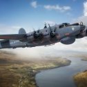
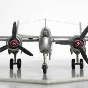
Hi again, from my trunk of memories, some photos of the really hard to build 1/72 Mach2 Breguet Alize. A sort of kit nicknamed "just for machos" 😆 . Need first a lot of putty, use of epoxy to fix better the unions. and also a bit of investigation due the sparse assembly instructions. but let´s go with the photos: the only one pieces tree provided, also remember the clear part needs to be polished a bit only a photo of the process.. after a lot of patience: the final result, I used Humbrol paints, decals came from a Model art sheet due the kit provided are fragile and translucent: conclusions and recommendations: 1. as a limited run kit you need a bit of experience, inspiration and a open mind to try new techniques and tools. 2. the decals need to be reemplaced due the low quality provided with the kit. 3. and the last advice is remember to investigate about the subjet to get the right informations related. (thanks Internet, the new Alexandria´s library) cheers from Central america. Carlos20 points
-
Hi, I just completed this new model from Hobbyboss. Has a few problems with parts that do not get mentioned in the instructions, some you can find a home for as you can see them in a diagram. Hopefully Hobbyboss can sort this out with a correction as they had to with the first issue of the M911 C-HET with Talbert trailer that had a few incorrect sprues.18 points
-
This is my first kit completion for more than half a year! I decided I wanted to do something fairly straight forward to get me back into the hobby and this 1/48 Tamiya Stug was just the ticket. The only things I added as extras were the PE grills from Hauler, a bristle from a paintbrush, some cotton and a bit of stowage from a part used Tamiya Jerry Can set. As usual, everything was painted with a variety of paint brushes, as I don't own an airbrush. I only use acrylic paints, mainly from Revell, Humbrol, RailMatch and Citadel. I use water to thin all my paints. The mud product was from Vallejo. The Work In Progress thread, if you are interested, can be found HERE. The photos above were taken against a plain white backdrop. The photos below were taken with the model on a grass mat with a sky photo backdrop: I really enjoyed the build and, as you might have guessed, I also enjoyed taking ALL the photos of it. Part of the enjoyment of this hobby for me is trying to get reasonable photos of my builds. Thank you to everyone who took the time to comment and offer suggestions in my build thread. Comments and suggestions are always welcome. I am hopefully going to soon start another 1/48 Stug build, but this time the Ausf.G version, again from Tamiya. Kind regards, Stix18 points
-
I hope this isn't too low-effort for the car forums I made this today as I didn't feel like working on any of my aircraft projects. Chassis is a tamiya 1:72 corsair drop tank Wheels are from revell 1:144 A320, sanded to proper shape Exhausts are cut from some revell 1:72 lanc' exhausts. And some other random bits and pieces for the very simple interior and suspension. Overall, I spent a day on it (with some breaks) so a very short build time. Anyways, here are some photos of the very simple build: Trying to select parts... Initially I was thinking of using some hurricane wheels as the rear wheels, this was changed as I saw most belly tank racers have 4 very similar wheels (if not identical) Construction begins! And here's the finished thing: It's really simple but I think that's what makes it fun. It's tiny! A very simple weekend build but I wanted to share it because I enjoyed making it16 points
-
Hi folk's,another HB easy kit and for me the first Wildcat I've done in a later scheme,brushed in Tamiya sea blue then medium blue passed over with the airbrush I used some weathering pencil's to pick out gun streaks and panel lines for the first time about three hours in total over the last week to complete for the Salty Sea Dog GB.Many thanks for looking in.16 points
-
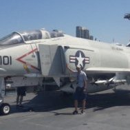
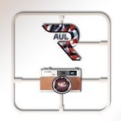
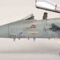
Hellenic Airforce F-4E Phantom II (AUP)15 points
-
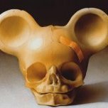
Another shelf of doom project done 😊 Phönix DIIa KuK Kriegsmarine 1918 MAC 1/72 The kit is an interesting build some good bits some not so good - decals which disintegrate on contact with water and the engine with minimal details in particular. Im happy with it in the end though14 points
-
Wow, I never realised there were so many pink warbirds! I'm pretty sure that my granddaughter (Leah) is thinking of a nice bright pink, kinda like the Barbie Corvette. (I think she got this idea because she saw a bottle or two of Gunze H19 in the rack - now that's a bright pink.) That P-40 might be the ticket, as she likes the shark's teeth on some of my models too. I'll bounce these ideas off of her and see what she thinks. I'm curious myself about that pink Mirage III. Time for some research... ***** Stickering is continuing. I managed to make the red around the intake lips with decals. Airfix think that a 2mm wide stripe that is straight as an arrow will somehow conform to a surface that has dissimilar curvature in two directions. Someone needs to go back to geometry class. My solution, convoluted as it is, was to take 1mm wide stripes and use two, adjacent to each other, on both the outside and the inside of the intake lip. These narrow stripes will curve, and the resulting wrinkles can be eradicated with Micro-Sol. The inboard straight red stripe on the fuselage side is from the kit and is about 1.5mm wide. It was way too long however, and had to be nipped. The forward edge of the intake lip was painted with Gunze H23 Shine Red as it matched really well. The Danger chevron came from the Xtradecal sheet. Anyway, it'll do. Although working with the thin strips of red stripes was a pain, I think it was easier than trying to mask this. The checkers are on the port side of the fin, but I can't show them to you until I apply the remaining 2 litres of solvent to get them to snuggle down onto that rudder. Getting the wing decals to go down over the vortex generators was bad enough... Cheers, Bill14 points
-
Hello everyone! Here is my first kit of the year, built for the "Minicraft Remembered" Group Build in the Kampfgruppe144 forum. It's Minicraft's 1:144 North American PBJ-1J Mitchell built as 64973/"O", of VMB-612, US Marines, at Iwo Jima, from April to late July 1945.. I was hoping to make this a quick OOB build but it dragged on for more than a month-and-a-half due to all the modifications and improvements needed to make this old Crown kit more accurate. These were (in no particular order): - Reshaping the nose canopy part, which was completely wrong, and getting the "Hose Nose" to blend in properly. - Adding the Matador Models white metal cockpit parts. I replaced the sticks for proper steering controls from stretched sprue. - Completely replacing the side gun packs which were oversized and too shallow. - Adding the armour plates below the main canopy. - Lowering the main wings 2mm. - Adding the two blisters on the fuselage spine. - Elongating the fairing to the tail gunner canopy. Replacing the tail gun barrels. - Remaking the tail bumper. - Relocating the underside bullet aerial. - Adding a retraction arm and scissor link to the nose wheel leg. Thinning the u/c doors. - Making the various intakes and landing lights along the leading edges of the wings. - Opening the cowlings and adding 3D-printed engines. - Remaking the intakes above the cowlings and adding the missing exhausts. - Thinning and reshaping the propeller blades. - Adding underwing HVARs taken from an AFV Club F4U kit. - Replacing the wing probe. It was fully painted and varnished with brush. I actually enjoyed all the work involved and am pleased with how I solved some of the problems. Above all, I am very happy with the end result, so much better than had I built it OOB. Thanks for looking and all comments are, as usual, welcome. Miguel13 points
-
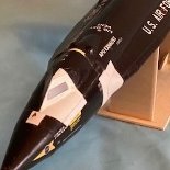
I’m new here but thought I’d post my latest — a cardmodel build of the X-15A-2 with full ablative/sealant. The basic model is available online but I also scratchbuilt a number of items to improve accuracy. I also resized parts from a 1/32nd-scale cardmodel of the X-15A-2 and used them as templates to make new parts. This build depicts the X-15A-2, 66672, as it looked on mission 2-53-97 on 3 October 1967 when Pete Knight made his speed-record flight. Markings on this particular flight differed somewhat from the previous two times the white X-15A-2 took to the air (one of which was a captive flight). I also added pink streaks to the underside of the wings and tailplanes to replicate the streaky appearance on the real vehicle. The white sealant was not sprayed on the underside of the wings and tailplanes as heavily as the top surfaces, and the streaks show up in photos from the three times the X-15A-2 went aloft. I hope cardmodels are ok here….13 points
-
Here she is, big and bold.... Built from the box, with only Brass U/C legs added as she is a heavy model. I was thinking of some weathering, but concluded that as this was a post German Surrender repaint the airframe would have been quite clean. You will notice some transfer damage: the Airfix transfers had not aged well, especially the big ones. Despite Microset they cracked in places. Hawker Typhoon Mk.Ib MP197 of 245 (Northern Rhodesia) Sqn RAF. The blue and white tail band and white propeller base and blue spinner was applied in Early summer 1945, before the Squadron was disbanded in Germany on August 10, 1945. I also like the mouth around the radiator. MP197 was the usual mount of F/L Harrison Taylor 'Moose' Mossip DFC RCAF until he was killed on 7 March 1945. 'Moose' was flying JP936 and during an attack on a train near Amden his aircraft hit high-tension cables and he was killed. MP197 then became the personal aircraft of 245's CO, S/L Tony Zweigbergk. The full build story is here:12 points
-
One more card X-15 build in 1/48 for today…. This is the first X-15, 66670, as it looked on its last flight — the 199th and last flight of the X-15 program. By the end of the program, technicians had essentially stopped reapplying painted markings after flights. Paint turned into a gooey mess at the X-15’s speeds anyway. On its last flight, 66670 carried only the U.S. AIR FORCE (albeit heavily weathered) on the side tunnels, the serial number on both sides of the dorsal tail, and camera targets on the upper surface of the tailplanes. Although there were no national markings on the wings, technicians either inexplicably repainted the “NO STEP” markings on the flaps, or used flaps that had been in storage. (Mixing parts from one X-15 to another was not uncommon.) The basic model is available online, but I had a friend do a “repaint” (common in cardmodeling) to represent the last flight. The model was in 1/72nd scale, but I enlarged it to 1/48th. I added a number of scratchbuilt items to improve accuracy. Among the added items were the wingtip experiment pods and the experiment box behind the tail. After its last flight, 66670 was placed in storage and then shipped to the Smithsonian; it is displayed today at the National Air and Space Museum in Washington. Before being shipped to the museum, NASA repainted markings on the vehicle.12 points
-
My build of the Avis 1/72 Short S.1 Cockle (BX 72031) The Avis kit provides both civilian and Air Ministry versions of the single prototype. Short didn't proceed further due to it's poor performance. In 1925, the rudder, fin and tailplanes were modified followed by a loan period with the Air Ministry when it was used for trials at the Marine Aircraft Experimental Establishment (MAEE), Felixstowe and given the serial number N193. It flew a few times before Short Brothers installed more powerful engines in 1926 and returned the Cockle to Felixstowe. It was purchased by the Air Ministry but only flew one more time before being used for corrosion testing. This was a build that was NOT stress-free thanks to my carelessness. I put my freshly-painted build to one side but I didn't ensure it was in a stable setting and it slid off and the result of it's maiden flight test left this result, ironically much in the spirit of the full-size subject that probably didn't even get that far off the ground on first trials: Anyway, I got it finished in the end: Dave12 points
-
Ok well that's enough fun for one morning. I think this is halfway decent. There still a bit of a bulge on the lowest part near the door. But I think the overall look is fine. Now this, three more times. Boy, this shell is going to eat up a lot of filler, primer and sand paper.12 points
-
Weekend update! 🤩 A flurry of excitement at the bench as my favourite bit kicks into gear. Ahhhhhh, paint. last time we had just finished the dark squiggles. Now time for some high points. Bring in the white!!!! I’m just picking out the middle of the panels where more bleaching may occur. I’m not being to precise with the strokes (passes) as I want that messy look. Here are some close ups so you can see what I’m doing. Overall I’m happy with the way it’s going. Here are some of the underside. Obvs this will be less faded overall. Now time for colour. This is going to be tricky and fun. I want her to look as worn as the real thing but not too much as I don’t like the finish so it’s going to be a bit of artistic licence on my half. so first off choose the blue. It calls out a quit bright blue on the sheet but the underside in real life is all over the place so I’m going for somewhere in the middle but edging toward more blue as I like the contrast. 💙 I’m going for the one in the middle. 🤩 Off we pop!!! The thing with a dark pre shade is that it really shows through. You have to trust the process and lightly pass over the bits you don’t want more and more as you build up colour. Oooh by the way you can see here where I have fixed the droop in the “elavons”? I think that’s right? 🥳 Thanks @Brandy and @Fritag. Eventually we arrive here. just a nice amount of wear but a hell of a long way to go. I had to do some ad hoc filling as this bit was just a little too much for my liking. And there we are. I bit of white added to tone it down. And in a more natural light. Weathering and filters and lord knows what else before I’m done. 🥸🥳 With a blast of TS-13 you can see what a good job the Mr Levelling thinners has done to the Tamiya acrylics. That got left to dry before moving on. More done tonight but I’m pooped so I’ll continue tomorrow. Thanks for checking in on my little build and I wish you all a happy weekend. all comments welcomed. Take care and as always. Happy modelling. Johnny.12 points
-
I forced myself to look at one of these blighters. I chose the Tutor. The butt joints are annoying, doubly so when the joining surfaces on the fuselage are barely defined. There’s also a small dihedral on the lower wings, matched by the upper ones. It needs patience and care to get things so they align in all the different planes and are not completely out of whack anywhere. Getting the lower wings in place, then, will be key to ensuring all the flying surfaces and fuselage are square and true. Ish. I had already decided to pin things together. I thought I’d be clever and use thin wall brass tube through the fuselage. Brass wire could be passed right through and into the wing roots, helping things to align. Yeah, well, it sort of worked. No worse than just sticking the wire straight into a drilled hole. In a desperate attempt to work out the dihedral angle, I resorted to drawing a line as square as I could on the handy front view line drawing in the instructions. Of course it’s not the right scale for the kit parts. Why would it be? I decided angles were much too much like jommetry, and measured the gap from bottom wing tip to the alignment line. More or less 2mm, and as I’m reliably informed by my smarter other half angles are angles no matter the scale. The kit parts are actually only a teensy bit bigger than the drawing, so I went with it. I found some lolly sticks which happened to be more or less 2mm thick. If I could hold the fuselage square, the wings should sit at the right angle and - importantly - remain symmetrical. Cue much faffing about. A while later I got to here. The tail plane parts have also been pinned. The horizontal stabilisers are a single part, but with no alignment to centre it on the fuselage. The fin and rudder are also vague. I shall leave things so the CA can set properly, then see if the wings need a tweak. Then some filler will be required. As sometimes happens, I have gone off piste and built things out of sequence. The undercarriage should have been fitted before the wings. Like that wouldn’t have been a world of hurt, with butt joins all over the shop and thin plastic parts just waiting for an excuse to snap. With lower wings on, I’ll have some chance of getting the wheels aligned and square. I hope. I suspect some further brass pinning will be needed, too. I’m really not enjoying this build, and not just because it’s a biplane. In fact, while being distracted by tiny bombs and false hangar fronts this past few weeks, I came perilously close to being hijacked by a Hampden and a pair of Wellingtons. I don’t need more part-started kits littering the place. I’ve got enough of that in the day job! More soon, I hope.12 points
-
Hi all, The latest build. An awesome kit with near perfect fit. Typical Tamiya. Out of the box with the exception of Eduard seatbelts. I also used Eduard canopy masks. Cheers for now.11 points
-
Hi everybody; for those following the 453rd BG Museum builds, here's my second entry after the P-51D I built and delivered to the Museum in Old Buckenham last year. For those who don't know what I'm talking about, a search in the forum for "453rd BG Museum build" will provide the whole back ground story Anyway, this is the second kit Jim (the Museum curator) sent me a couple of years ago, and it's about time I started building it! The kit is the well known Tamiya 1/48 Republic P-47D Thunderbolt "Bubbletop": Let's have a look inside the box, shell we? Three main sprues with lots of details already (note in the last one there's a pilot figure and three different kinds of propellers), plus tow additional sprues with payload and tanks and other details Transparencies Huge decals/stickers sheet: (won't be using many of those.... ) Jim also added this AM PE fret: And this is the specific airframe I'm going to build: Also shown a this link: https://www.worldwarphotos.info/wp-content/gallery/usa/aircrafts/p-47d/P-47D_42-26637_Kokomo_Kepner_2.jpg What is peculiar about this aircraft, besides the nose art, is that it was used in a training unit and was the personal mount of Maj. Gen. Kepner; it was kept to a minimum load possible, so no drop tanks or any other hanging bits and pylons, and the outer gun barrels were removed and blanked out, leaving her with 6 machine guns in place of the standard 8. Construction has not started yet, but will soon with the cockpit; in that regard, there's a nice thread right here on BM on how confusing the situation about cockpit color is on this AC, but I think I'll go with the general consensus reported there and paint it Dark Dull Green; now, if only I had a clue about how that color looks like..... All comments and advice most welcome Ciao11 points
-
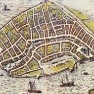
For me, the Victorian Age will always be the pinnacle of Europan history. If I had a time machine, I´d go bach to 1898, to Britain, Germany, France, Belgium or Italy. Such a wonderful time, Europe at the peak of imperial splendour and might, Britain not yet ruined by WWI, France risen again after the defeat of the Franco-Prussian war, its 3rd republic in full swing, Germany celebrating the 10th year of Emperor Wilhelm the 2nd... I could write on and on about that time, but that is a ship forum so let me say that the world has not seen more interesting ships then in the late ironclad/pre dreadnought period. Unfortunately, this time period has been criminally neglected by all mainstream plastic model manufacturers (with a few exceptions) so I had to turn to small Russian resin model manufacturer Combrig. After months of tinkering, improvisation and (a little) frustration, I finished HMS Victoria. While some flaws remain the ship turned out quite beautiful I think, echoing, I hope, a tiny little bit of that Victorian splendour, majesty, beauty and power. I want to thank everyone who followed me on my little construction journey on the "work in progress" thread, who inspired and motivated me to continue and at last, to finish her. Comments and criticism are most welcome. BTW some pictures turned out a bit greenish, that is an effect of the light, the white portions are indeed white...11 points
-
This is my build of the Italeri 1/72 OH-13S Sioux. The Sioux was used as an early Aeroscout in Viet Nam until replaced by the Hughes OH-6A Cayuse. For an Italeri kit this one was a fairly pleasant and quick build*. It easily breaks up into cabin, fuselage and engine subsections. For once the transparency fit almost perfectly, although the doors to bubble fit was bad, But since they were flown without the door that was not a real issue. I did use the door as a sort of mask to protect the interior of the cabin when spraying and just used Microscale Krystal Klear to fill the gaps. As a helper I also used the CMK upgrade kit for various and sundry interior and engine parts. All together it was ~10 day build. Next up is the Italeri OH-6A Enjoy. * As noted elsewhere the Italeri cabin is way oversized for the OH-13S, but I chose to ignore this since it would have been very difficult if not impossible to correct.11 points
-
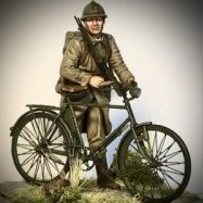
Let me introduce the old work of VID soldiers - The capture standard of british 69th by french 8th Cuirassiers at Quatre-Bras, 1815. This is VID soldiers metal figurines, 60 mm (1/30 scale)11 points
-
Well it seems I’m awake again. Out again in old Blighty today, but before that there’s unfinished business. Masks were next on the agenda after the top coat had dried. And tail side. Lovely. Now I’ve been thinking about the ware and tear on this and also thinking about decals. Now there are a few options. Paint ‘em. (Steady on @giemme) cut bits out before sliding them on. Or I saw this while cleaning yesterday. hmmm I wonder if I can sand back a decal to give what in after??? Some tests are afoot. Any road I used the trusty mr mask Neo to mess up the demarcation line. then went at it with a mix of paints and styles. (I’m going all over first so I can have this coat show through the darker one when chipped / flaked / faded.) first coat more juicy. Then more of a “buff” duller coat. Then more darker juice but just in the middle of the panels to bring it back. you can see what I mean here. Outer wing panels done inner not so much. This is feeling good to my eye. A nice starting point for the rest of the cRaZy. And everything looking seamless. (Phew) Any lumps or errors will be lost in the coming madness but for now we are in the eye. I’m liking the dark mess showing through. After we are dry I need to mask for the darker camo. So here we are. Still night time in this shot and I haven’t seen her in this mornings light. fingers crossed it’s not changed. More soon chums. Take care and as always. Happy modelling. Johnny.11 points
-
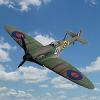
#7/2023 My dad hasn´t done a British aircraft, at least with British markings, for a while. Now it was about time. Great Tamiya kit, also used Tamiya´s PE set for the rigging. Not a bad idea, worth a try and didn´t turn out too bad. But for the next bipe, my dad will stick to elastic thread again. Painted with Tamiya XF-2 White, AK Real Color Extra Dark Sea Grey and a selfmixed Dark Slate Grey. EZ Line for the antenna wires and the tailplane control wires. Build thread here https://www.britmodeller.com/forums/index.php?/topic/235121011-deadly-stringbag148-fairey-swordfish-mkii-836-nas-royal-navy-fleet-air-arm/ Model shows an aircraft that served with 836 NAS aboard the merchant aircraft carrier (MAC-ship) "Amastra" 1943/44. DSC_0002 by grimreaper110, auf Flickr DSC_0003 by grimreaper110, auf Flickr DSC_0004 by grimreaper110, auf Flickr DSC_0003 by grimreaper110, auf Flickr DSC_0006 by grimreaper110, auf Flickr DSC_0007 by grimreaper110, auf Flickr DSC_0004 by grimreaper110, auf Flickr DSC_0009 by grimreaper110, auf Flickr DSC_0011 by grimreaper110, auf Flickr DSC_0012 by grimreaper110, auf Flickr DSC_0013 by grimreaper110, auf Flickr DSC_0014 by grimreaper110, auf Flickr DSC_0015 by grimreaper110, auf Flickr DSC_0016 by grimreaper110, auf Flickr DSC_0007 by grimreaper110, auf Flickr DSC_0022 by grimreaper110, auf Flickr DSC_0005 by grimreaper110, auf Flickr DSC_0023 by grimreaper110, auf Flickr DSC_0024 by grimreaper110, auf Flickr DSC_0025 by grimreaper110, auf Flickr DSC_0026 by grimreaper110, auf Flickr DSC_0027 by grimreaper110, auf Flickr DSC_0006 by grimreaper110, auf Flickr DSC_0028 by grimreaper110, auf Flickr DSC_0029 by grimreaper110, auf Flickr10 points
-
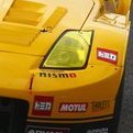
The Yamaha XV1100 Virago 'factory custom' bike; you love 'em or you hate 'em. I don't love 'em. However, youtuber Kota Scale Model made me think that I might be able to do something a little 'interesting' with the base kit. Kota may be able to build a bike in thirty minutes in his videos, but this was more of a challenge than I thought it would be. I had to put it aside on a couple of occasions while I had a think about how to do something, but it got there in the end. The rear wheel, engine and hand grips have not been altered. Everything else has been adjusted or scratch built. All the model 'chrome' was stripped and re-done with Ammo A-Stand chrome, and various Alclad and Vallejo Metal Color shades. The yellow is Mr Color RLM04 and the speed-blocks scheme harks back to the days of King Kenny Roberts as he blasted around the flat tracks or diced with Barry Sheene on the GP circuits. The final gloss coat is provided by Zero Paints 2K clear coat. Rather than list all the changes I made, here are a few photos of the completed model: Now it's time to go and build something nice and easy out of the box.10 points
-
This is my build of an old 1/72 Hasegawa kit of the Grumman EA-6B Prowler. I have finished it as an ICAP-I version flown by VAQ-134 onboard USS Enterprise in 1978. Here is a link to the build thread. The only grumble is that in this boxing Hasegawa tinted all of the glazing when in fact the windscreen was left untinted in real life. I replaced the kit seats but did not go in for the rather expensive complete interior and am now glad because quite frankly the tinting pretty much hides most of the detail. I see from the pics that I have forgotten to add the ejector seat face curtain pull handles Not a bad kit and easy enough to build - in fact I think the painting took longer than the assembly. Pete10 points
-
That was a good one 🙂 In the past couple of days, I've been doing the surgery on the other side. Sober, I might add, although it definitely looks like the surgeon may have had one too many More scars but we now have a solid shell again. Before glueing that cutout back in place, I made sure the rear quarter and door panel lines lined up correctly with the ones on the other side. As you can see I worked around that fuel filler opening. Now, the next tasks are filling up the gaps in the front doors and getting some shaping done to blend the material in. Also, before I start filling and removing the scars, I'll have to do something about the fenders and side skirts which, though correct for the gti body, are too pronounced for the GL version. The side skirts just need to be toned down some, but these wheel well surrounds or whatever they're called also need blending in with the body. That's because on the gti, they're plastic parts, while as on the regular version, it's just a flared part of the body shell. I think it will take some time to get those to look right but we'll see. Anyway, I want to do that before I start filling seams, I will be flexing the shell when handling it and I don't want to cause cracks in my fillings.10 points
-
So this was my first 1st time trying to print/paint something this big. The sanding and filling wasn't as bad as I thought. I knew I'd never get the paneling right and I tried to do some weathering on a test piece and it just looked wrong and I ran out of time as this was for a friend's birthday (fun and games getting it to the pub ) Getting all the electronics in for the remote control light up globe was an amazing squeeze, next time I'll remember to add room for all the wires not just the circuit boards. There are also a couple of other mistakes, /cough decal placement, but at least I know how to print my own now Thanks for watching WIP here 3D model here9 points
-
Sikorsky CH-54A Tarhe US Heavy Helicopter (35054) 1:35 ICM via H G Hannants Ltd With the advent of the helicopter, their ability to rise vertically into the air led them to lifting heavy loads, and by the end of the Korean War, there were already Heavy Lift choppers in service, most using piston-engines as their motive force, which was a limitation both in terms of power and reliability – a very important factor when you aren’t flying, but are instead beating the air into submission with your rotors. The peculiarly ungainly-looking CH-60 Mojave was reaching the end of its service life, and Igor Sikorsky had already identified the need for a very heavy lift helicopter with the S-60 that was powered by WWII era radial engines. The design was the basis for the Tarhe, but updated and given the more powerful and reliable turbo-shaft engines that were just coming into production. The engines for the nascent CH-54 were created in conjunction with Pratt & Whitney, adapting one of their new JT12 jet engines to their requirements. In an effort to keep the weight of the airframe down, the designers gave the Tarhe a cut-down skeletal fuselage, with only the crew compartment boxed in. This compartment also contained a rearward-facing cab that gave the crane operators an excellent view of proceedings, as well as limited control over the height and attitude of the airframe, due to the fact that the CH-54 had an early form of fly-by-wire that allowed the duplicating of controls in the secondary location, but with the effectiveness of the controls lessened to reduce the likelihood of accidents due to sudden movements caused by the crane-operator. The advanced control system also gave it such luxuries as altitude control, reducing the workload of the pilots during extended hovers. The US Army recognised the potential of the type after a short testing phase, who took over 100 airframes on charge that would see extensive use in Vietnam. A civilian version was created too, called the S-64 Skycrane, while in army service it was often referred to as just ‘The Crane’. Because of its size, The Crane was capable of carrying enormous loads that were hitherto impossible to lift vertically, if at all. It was able to carry a Sheridan Tank, an M101 Howitzer, or up to 90 fully kitted out soldiers in a passenger pod that could be slung under the skeletal bodywork. There’s some fantastic diorama fodder right there. The type was eventually withdrawn from service in the late 80s, as the airframes were ageing and Chinook was taking over in military service, finally leaving National Guard service in the early 90s. Due to their usefulness however, many of them were bought by civilian operators, especially Erickson Air-Crane of Oregon, who also took over type approval to ensure their ongoing airworthiness. The Kit This is a brand-new tooling from ICM, and while I initially rubbed my chin sceptically over the chosen scale, it makes an awful lot of sense when you consider what it can carry. It’s the first of its kind in this scale, and in fact we’ve not been very well served in any scale as far as the Tarhe goes, other than a really old kit in 1:72 from another manufacturer. It arrives in a long top-opening box with a wrap-around painting of the type in action, and inside are a deceptive two lower trays with the usual captive lids, all of which is held in by tape. Take care when opening the box, as it could surprise you when the second box drops out. Once the boxes are open, the sprues have been spread evenly across the two trays to reduce the likelihood of damage to some of the lovely detail that’s within. There are fourteen sprues in grey styrene, one of clear parts, a relatively small decal sheet, and a moderately thick instruction booklet printed on glossy paper with colour profiles in the rear. It’s difficult to get a feel for the scale of the finished model from the sprues, but the length is stated on the box of 774mm or 30.4” long, and 225mm or 8.9” tall. The width isn’t given, but each rotor is 28cm or 11” long, so allowing for the extra width of the centre boss it should be a little more than twice that wide. Detail is excellent, as we’ve come to expect from ICM in recent years, with finely engraved panel lines, raised rivets where appropriate, and crystal clear canopy parts, which will be very visible on the finished model. Without a shadow of a doubt someone will manage to create a diorama that uses the cables to support the finished model above its load to give the impression of flight, and if they also manage to make the blades rotate, they may just achieve modelling godhood. Construction begins with the stepped cockpit floor, which is kitted out with rudder pedals for both pilots, adding the instrument panel and supporting centre console with decals to the centre, then fixing collective and cyclic sticks in position, followed by the seats that are each made from rear frame, seat pad and back cushion, locating in holes in their adjustment rails moulded into the floor. Another seat is made up from a solid base and two cushions, gluing in position on the lower section of the floor, facing aft and forming the first part of the crane operator’s cab. A partial bulkhead separates the front seats from the rear, adding another to the side of the seat that has a small console with joystick sprouting from the centre. Another L-shaped column is added on the inner side, and a short frame with an instrument panel and decal attached to it at the side of the cut-out, which is fleshed out with a pair of curved bulkheads. At the front of the cockpit, the nose cone is mounted in front of the instrument panel, then the sides and underside of the cockpit structure closes in much of the area. Turning the assembly around, the rear is closed in with a panel that wraps under the edge, and under the crane-operator seat, a foot rest with twin supports is slotted into the edge. The back of the cockpit has a lot of glazing, starting with five radiused panes in the starboard corner, one more on the port by the crane-op’s seat, and a large wrap-around section enclosing the operator’s cab. Much of the fuselage of this behemoth is skeletal, and is built up as a separate assembly, including internal bracing to ensure your Tarhe doesn’t become a Droopee. The process starts with the underside of the fuselage structure, which is made from three overlapping lengths that have location grooves for the bracing that comes later. Firstly, the winch is made from two halves that form a drum, capped off with two nicely detailed parts that turn it into a bobbin, which is supported between two angled trunnions that are each laminated from three parts, and braced at one end by rods and by the bobbin at the rounded end. It is glued between two vertical braces that have two more braces slotted in across the front and rear of the winch bay, fixing two exterior panels to the end of the cross-braces, plus another that is slotted in nearer the front. Take care here, as there are two slots, and the aft-most is the correct choice. At the same time, a cross-brace that supports the main landing gear sponsons is added from underneath, and this slots into all four thicknesses, as does another short brace behind and one more in the front, making the assembly stronger, and once it is glued to the underside of the fuselage it should be very strong. On the tapering tail section two more bulkheads are shown being added, but in the next step a longitudinal brace is shown already fitted, which I suspect is part D11, but test fit to reassure yourself when you build yours. The two tail sides with moulded-in fin hides the tail internals, joining together at the tip of the fin, and secured by adding the rear surface, and cutting a raised area off the underside. The topside of the fuselage is then boxed in with three panels, the largest having a hole in the centre for the rotor head later. The full length of the beast can be seen for the first time now, when you mate the cockpit to the front of the fuselage, gluing the side extensions to the bare section to create one assembly. An overhead console is decaled and detailed with levers, and is fixed to the rear bulkhead of the cockpit alongside another, after which the cockpit roof is laid over the area, followed by the windscreen and side doors that give your Tarhe a face. Two small two-part “ears” are made up and inserted in recesses near the rear of the cockpit, as are a couple of other small humps and bumps, the uses for which will become clear later. On the port fuselage side, a thick trunk of cables is fixed to the side and overlaid by a pair of C-shaped assemblies that are each built from three parts. The CH-54 had long legs that allowed it to pull its loads close to the spine to reduce sway, and these are next to be made, starting with a pair of two-part wheels, and the sponsons that support them, each one made from four surfaces, plus the struts, which have a two-part sleeve around the upper area, separate scissor-links and two tie-down hooks, fitting to the end of the sponson by the flattened rear of the outer sleeve. The nose wheel is also two-part, and fits on a short oleo with a one-part scissor-link under the nose. The winch head is also two parts and is added to the winch mechanism while the main gear sponsons are slipped over the supports and the nose wheel is put in place. The tail rotor head is a complex assembly that should remain mobile after construction, made up from eleven parts and fitted on the back of the tail fin along with a small bracing rod at the front. There are also several external trunks added individually on the starboard side and down the leg sponsons, some of which are overlaid by a protective panel near the front, and yet more small lengths are dotted around all over the place, making for a complex, detailed surface that should look more realistic than moulded-in alternatives. The drive-shaft for the tail rotor is also external, and runs up the back of the fin through some additional brackets, and terminating at the bottom with a four-part universal joint. More scabbed-on panels are fitted to the back of the fuselage, and a pair of optional aerodynamic fairings are supplied for the sides of the main gear sponsons. This isn’t even close to the final layer of detail yet, but we take a break from detailing to build the main rotor head next. The rotor-head starts with a bell-housing that has two input shafts from the twin turbo-shaft engines, the main portion of which is two parts, plus two-part end caps that is then placed on a circular base, and has the shaft cover and ring fitted to the top, adding a number of actuators and rods to the side, plus a housing with pulleys and equipment that mounts on the back of the head. The basic assembly is then mated with the opening in the top of the fuselage, after which there are a host of small wires/actuators/hoses that link the two assemblies together. A scabbed-on box is fixed to the fuselage behind the rotor off to one side to accommodate the drive-shaft for the tail rotor later, and a bulwark slots into a groove just in front of the rotor-head, followed by the drive-shaft, which slots through a support and dives through the tail to emerge behind the fin at the universal joint. A two-layer cover is placed over the drive-shaft around half way back, possibly to protect it from blade strikes, but it’s not the only piece of equipment that is sited on the fuselage top, which includes what appears to be a radiator assembly and some kind of exhaust, both installed behind the rotor-head, an area that is getting busy already. More parts are added further enmeshing the various assemblies, then it’s time to build the two engines. The Pratt & Whitney engines are identical in make-up until they reach the exhaust stage, which is handed. The front section is made from thirty-five parts before the handed exhausts are made, each one a mirror-image of the other, and built from eight more parts. The motors are mounted on the top deck with an M-brace between them, adding a few more small parts around them, then building up two intake filter boxes from sixteen parts each, handed to each side, with a scrap diagram showing how they should look from the front. They mount in front of the engine intakes on the ears we made earlier, and have two Z-braces front and rear between them. There are four auxiliary winches for load stabilising placed around the front and rear sides of the fuselage, with a four-part assembly making each one, and locating on a pair of brackets moulded into the fuselage sides. More detail is applied to the cockpit in the shape of four clear lenses underneath, a towel-rail and blade antenna, two more externally routed wires around the rear, and crew step plus three ladder rungs on each side, with two more around the rear. Grab-handles, door handles and windscreen wipers are next, followed by yet more grab handles on both sides leading up to the cockpit roof. More aerials are fixed at the root of the tail boom, and at the very rear, a three-part bumper is fitted under the fin, then an asymmetrical stabiliser is mounted on the opposite side of the fin to the tail rotor. Most traditional choppers have two rotors, and despite its size the Tarhe conforms to that layout, and the tail-rotor is first to be made, starting with the two-part rotor base that accepts the four individual blades, and a two-part actuator crown in the centre. It fits to the axle and should be able to rotate if you’ve been sparing with the glue. That’s the easy, simple part over with, now you must do it again on a much larger scale and with six blades. Work starts with the axle, the lower end of which slips through a centre boss and is covered by the six-point star assembly, which has another smaller star fixed to the centre, six D-shaped inserts added to the tips, and T-shaped spacers added vertically to separate the top rotor “star” from the bottom. The top portion is made up identically to the lower apart from the spacers, then it is closed over the rotor holders after gluing them in place on the lower. Each blade holder then has its four-part actuator mechanism installed over the top, and the whole assembly is topped by a three-part spinner cap. The final act is to insert each of the six blades into the holders, then drop the completed rotor into the rotor-head. Markings There are two decal options on the sheet included in the box, and unsurprisingly, they’re both green. Many of the decals are for the blades, but there are also national and airframe markings, plus the instrument panel decals and some stencils. From the box you can build one of the following: 67-18420, 273rd Assault Support Helicopter Company, Vietnam, 1968 67-18426, 101st Airborne Division, Vietnam, 1969 Decals are by ICM’s usual partners, which is a guarantee of good registration, sharpness and colour density, with a thin gloss carrier film cut close to the printed areas. Conclusion This will make a superbly detailed model, and its size will draw some admiring or envious glances if you take it to a show. Detail is excellent, construction is sensible, and it is a new tool of this monstrous machine. Very highly recommended. Available in the UK from importers H G Hannants Ltd. Review sample courtesy of9 points
-
The Zvezda kit of the earlier Su-24 built in Ukrainian markings Using Begemot Decals sheet No 72-040. This is an older kit, so quite simplified compared to modern day kits. Build wise not too bad, but a few seams around the forward fuselage and nose were a bit troublesome to fix. Underside colour is SMS PL02 white and the grey is SMS PL93 blue grey. The Begemot decals went on without any problems. Build progress video9 points
-
Thanks Col, Quite a few about in 1/48 but quite rare in 1/72. Most are quite expensive, some ridiculously so but there is a cheap one on e-bay if you don't mind paying £25 for postage from Oz, though that may tempt one or two of out Antipodean modellers! Can't quite remember when I bought this but around 5 years ago, maybe a bit longer, and I doubt I paid more that £12 ex postage. Anyway, it is finished - The fit was a bit fiddly at times but I am pleased with the result. Pete9 points
-
Good afternoon mates, Another short update. Thinking on how to recover from the foggy finish caused by the matt varnish, I thought ended up with a mix of Xtracrilics matt varnish, Future and alcohol. The percentage of Future in the mix, should have darkened a little the overall finish, neutralizing the foggy effect and, in the meantime, highlighting the contrast among different colours, expecially the “nose art”. Fortunately it worked and thus I ended up with a quite balanced finish. I also removed the masking from the canopy and now the pilot is visible. Here below a few pictures. As I didn’t like at all the last pictures taken with my new phone, when I had zoomed in to 1,9 :1, I decided to go for a 1:1 setting for the zoom and used a coloured background, as suggested by Giorgio @Giemme. Thanks for watching, Ciao Massimo9 points
-
I did some work on the rear metallics today. Starting with a coat of Xtreme Metals Steel and then bits picked out with Alclad Duraluminium and Dark Aluminium. This was followed by some coats of Alclad Pale Burnt Metal, Xtreme Metals Burnt Metal and Jet Exhaust. Leaving this. Thanks for looking, Cheers, Alistair9 points
-
Work has rather interrupted things, but a relaxing Saturday, hits of the 80s and a wee dram of something to lubricate the fine motor skills(!) and a bit of progress! I've added a small piece of clear plastic for the reflector sight, and secured the Falcon windscreen with woodglue. An absolutely perfect fit- the first time ever with a vacform! I also found a piece of old photoetch which I've used to dress up the radiator area before attaching the wings...beginning to come together! You can also see the attempt to dress up the wheel wells. I've also made a start on the props- a bit of cleaning up to do there, and drilled out holes for the intakes either side of the props. There'll be a bit of spot filling here and there, and I'll cut off the gun camera box which Airfix have in the wrong place. I'll forgive them that! Looking ahead, I'm going to have to do something about the cannon...luckily I have spare early style cannon from an Arma Hurri IIc kit, so that's sorted!9 points
-
Hi guys, just finished this one, Tamiya Honda RA272 in 1/20 scale. It is a race car from the 60s, the first Japanese car to win formula one. What really impressed me and I still can't believe it is that this car had 1.5L engine V12! Just search on YouTube to hear the engine sound, just incredible! The build went well, Tamiya usual quality. Used Tamiya paints for the non-metallic parts and Alclad for the engine. I didn't add any wiring/piping which is a pity, but I film in stopmotion the build process, and it would be difficult to also add wiring. Let me know what you think!8 points
-
Hi folk's not the proposed scheme but happy with the outcome,HB easy-kit late Wildcat.8 points
-
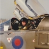
Hi everybody; some substantial update, at least, and even a bit of color (oh hey ) even if it's just black, in this report. Let's see: I glued in the PE slime lights from the Eduard fret I left off the tail ones, because they are going to placed on top of a decal, so they will have to be added towards the end of the build. I removed the Quickboost seats from their pouring blocks, cleaned them and dry fit: The pilot's one needed a good deal of shave off at the base to actually fit in, but that part part will remain completely invisible anyway once inserted, so loosing some surface detail there was no big deal. Here are the seats and ejections handles, primed with a few coats of Tamiya Flat Black, thinned with cellulose thinner Canopies: I masked them with the mask @Gene K designed and I cut from Oramask 810 using my Curio cutter I then added the canopy latches from copper wire, bent to shape and flattened with flat pliers (glued in with CA) Not perfect, but I don't have any spare PE for that, and since they are a very distinctive feature on a Phantom with open canopies, I thought they were better than nothing. These too received a black base coat Only inside for the central fixed frame, that was then glued in place, initially only starboard side because it needed to be pried open a bit to actually fit port side too So the cunning plan was, once set on starboard side, to gently push form the top and glue it in place with a drop of CA. When I tried that, it just popped off. Which ended up being a good thing, because I had forgotten to remove the inside masking Off that went, and I repositioned it, this time gluing both sides at the same time with CA ready for cockpit masking, once properly cured. the drop tanks received a flat black base coat and a gloss black one (Tamiya Gloss Black for some reason is not that glossy.... ), in preparation for some metal paint Masking for the cockpit and the air intakes to start soon, before I glue in the outer wings and give the whole model a good rub down with IPA, prior to black base coating. All comments welcome. Also, if anyone is interested, I started my second Museum build over here: Ciao8 points
-
Thanks both I thought I'd be varnishing this morning, then realised I had some more transfers to apply: That's the little pot of Klear. Opened carefully this time. I realise that I need to transport the model to Norfolk so I'm planning to stick the fragile bits on when I get to Jim's. Includes some PE: But these bits can go on now I think: Like this: How will I get the B17s (and maybe others) across the country? I was lucky enough to get a 'wine advent calendar' for Christmas: Empty now, of course (hic). Drink responsibly With the front cut to provide a 'lid' the insides, I hope, could be cut to hold the models: Fingers crossed.8 points
-
decals are from a special release of this kit by the Time Air Historical Society. The intended markings ended up in disaster courtesy of PointerDog decals, lesson learned; never again !!8 points
-
Preamble to the usual notes: I won't be starting any more builds now for about 5 weeks or so. Despite being made redundant part-way through this build, I had a prior holiday booked for 3.5 weeks to Japan for most of March this year, as I'll be 50 in June. Special year. Given that trip is unrefundable and uncancellable at this stage, I'm still going. And to be honest I could use the mental break. I have been to Japan before, and I know exactly where the model kit shops are in Tokyo. Both the ones for new kits, and presumably - if they've not closed down, the more interesting ones where the secondhand model kits are. I also know how to maximise suitcase space to cram in as much as possible, clipping parts from sprues to get two kits into one box. What's more, prices in Japan are much lower, typically about 50% of what you'd pay here for new kits and maybe 25%-70% of what you'd pay here for secondhand kits depending on the kit. Last time I went (2019) I saw but stupidly did not buy a Tamiya Nissan Primera for £20. And £25 was about the going rate (2019) for a Tamiya Ford Focus, and about £17 for a Hasegawa one. So I will still be buying - depending on what I find. Either I keep them or they end up on Ebay if I need the money, or possibly a mixture of both. Whilst I am there I am going to attempt to post some photos of these shops in the Vehicle Discussion section, if I can get them uploaded and linked using just my phone. Anyway enough of my life stuff, on with the Silvia. Background: The S15 Silvia is one of my favourite Japanese sports cars - certainly up there in the top 10. I find it to have a very elegant look. I bought this kit some 10 years before actually getting around to it, part of that delay was indecision over the colour. When I discovered Nissan Silver Moss not long ago whilst researching another kit, I knew I had my S15's colour and started immediately. Pros: Very nicely moulded, almost all of it fits together perfectly. Good wheels, tyres, glass parts and decals and the special edition with PE set made for some useful detail enhancements too. Bonnet is a seperate item making painting and polishing easier. Few seamlines and zero cleanup. Cons: No engine. The front bumper mounts are small and weak, and need reinforcement - a common problem with Aoshima kits, I've found. The seats are a bit slabby in appearance and don't really looks like fabric, more like marble. Most of the chromed parts are way too shiny. Verdict: Mostly excellent. It's one of the most straightforward kits I've built in a long time. Build notes: Built over the course of about 4 weeks in Jan/Feb 2023. Painted in Nissan Silver Moss. Clearcoated with Mr Hobby Premium Gloss. Aside from air valves on the wheels, built entirely out of the box.7 points
-
This is T-55 from Vojska Republike Srpske (Serbian armed forces) during civil war in Bosnia. Kit itself is quite good, without any shortcomings. I replace barrel with metal one from RB. Replaced plastic hooks, rails, headlight guards with self-made metal ones, added various pipes, tarp on turret and back of the tank, few jerry cans, ammo crates... Decals are from Bison decal. Fare warning! Their carrier film is almost non-existent, so treat them with some liquid film before application. Comments are welcome.7 points
-
Good evening mates, What shown in my last posts was referring to last week’s work. Now something more recent. Yesterday I decided to concentrate on the Sidewinders and GB 87 bombs. As explained earlier in the build, These war loads come from an F-16 B by Kinetic , together wit many other bombs, missiles and pods. Usual treatment : black primer, white mottling, followed by a coat of diluted base colors, then a coat of Future, ready for decaling. Decals are on a dedicated sheet, really beautiful!!! Another coat of Future to seal the decals, followed by a black wash for the sidewinders and a zinc chrome one for the bombs, to contrast the green. Ready tpo be fitted. To fit them, I drilled some holes in the pylons and glued some pieces of plastic rod to be used as locator pins. And finally they got into place. That was last night and I went to bed quite happy! This morning I had to chose from different options , but having already had the wheels’ bays’ doors around for a few years, I thought it was time to see them where they are meant to be, so with the help fo superglue , a toothpick and the liquid glue Tamiya green cap, I started with the upper front ones. I used a paper cushion at their back to hold them at the right height. Then, one by one, I added the other ones. Shes starting looking the part! Still remaining to be taken care off: Main landing gears, front wheel and doors, doors’ actuators, engines’ nozzles, navigation lights and various antennas….and the base but for today that’s it! Thanks for watching and good night!!! Massimo7 points
-
You want photos? Okay, you get photos. I make no apology for the state of this. While the engine, cowling and exhaust are intended to butt join on the stub of the nose - which I am not enamoured of but content to do - I plan to drill a hole in the stub to stick a stick into. This will make it easier to handle for painting. Lots of yellow to go on underneath. I will airbrush that. The camo, though, will be easier to brush paint in my usual fashion. Happily, the chosen scheme doesn’t appear to have shadow shading on the lower wings. Before that, some PE stuff, and I have to make the tailplane struts. Maybe next weekend. Maybe not. It’s not a particularly complex kit, doesn’t have many parts, but still throws all kinds of gaiety at the builder. What’s depressing is how many of the remaining biplanes in the stash are from short run makers. What joys do they have in store for me, one wonders. We do this for fun, don’t we?7 points
-
Let’s do this! Carpe the heck out of this diem, or something. I went round all the holes for the various struts. Some needed to be drilled out because of mismoulds, some needed drilling out because they weren’t even there, and the remainder were enlarged. I wanted holes a bit bigger than they needed to be to allow for wriggle room. I spent a while carefully extracting the outer wing N-shaped interplanes and cleaning them up so they looked respectable. I figured fitting these to the lower wings would set the various angles for the upper one. Here, I used some scrap card I had cut out some time ago, which just happened to be a right-angle. The struts appear to be perpendicular to the ground, so slightly angled to the wing dihedral. This mashup sort of worked. A while later, long enough for the liquid cement to grab, but not enough for it to set solid, I grappled the upper wing and main assembly to get one set of struts with glue applied. Carefully, inverting the shebang to lay it on the bench upper wing downside up, I wiggled both sets of strut locations into their holes in the top wing. Everything was still a bit floppy, but the liquid cement allowed some wriggle time. Carefully turning everything over again, the scrap alignment triangles were replaced to try to help the struts remain vertical. It will all be left alone to let things harden properly. It may need a drop of CA all round each strut location just to make it as rigid as possible. The cabane struts will be fun, although the aileron actuation rods will be a simple bend into place. As for rigging, well, let’s worry about that once painting is done. I promised myself I’d find a decent biplane construction jig. The stash contains a baker's dozen more of these pesky things. I know I could make something, but I get stuck trying to work out heights and widths and angles. Of course, now I decide to acquire one, they’re like rocking horse poop. Any pointers to decent jigs out there would be appreciated.7 points
-
Richiesta di aiuto. Ho creato un post con blogger con le foto dell'articolo, ma purtroppo non riesco a caricarle. Sarei grato se qualcuno potesse illuminarmi su come fare. Grazie per l'attenzione.7 points
-
Thank you Gentlemen for your words of encouragement, they are both motivating and inspiring. Now that the height and width of the front end has been roughed into place, it's time to turn my attention to the length of the front end. When I suggested this conversion a few days ago, a couple of members immediately stepped forward and offered to measure their Clubbies. I must say, that without those measurements, this conversion would have been much more difficult for me. So, Thank You, Keith and Trevor! The two key measurements were the length from the wheel arch/vertical pinchweld seam to the end of the wing, the second being the length of the bonnet. Both sets of measurements were exactly the same for these two measurements (A & C). However there were some discrepancies in the others. But when it was all boiled down to 1/24 scale, they were less than one millimeter apart! 👍 When the measurements are transferred to the body, it quickly becomes apparent that it's a little too long. Also note: When measuring the bonnet length, my starting point is the uncut gap between the bonnet and scuttle. This is another reason for cutting just forward of that gap, it's a much more accurate way measure. (The scuttle being the same for the Mini and the Clubman, you just have to hope/assume Hasagawa got that one right) Using my scribe, I set it to the roughly 3mm excess length, then transferred that to the back part of the assembly. Using my Dremel and holding my breath, I slowly ground off the excess plastic, being careful not to get it too hot. Thus melting or warping it. A little bit of self adhesive sand paper (120 grit) stuck to the side of a Bic lighter makes a wonderful sanding block for those long gentle curves. Also of note is the small "glue strip" added to the underside of the scuttle. This will also help level the 2 panels. Although, as I found out, the Mini and Sunny are of different thicknesses. A little shaving of the underside of the pickup bonnet was necessary to alleviate the issue. Although not really apparent in 2nd photo below, cutting the pickup bonnet into 3 pieces did help it "conform" to the Mini's scuttle. At this point the front end is held together with small amounts of super glue. When I have to grind off substantial amounts of plastic on a small, delicate pieces such as this, I like to tape them all together for added strength. If and when your Dremel catches it and it goes flying, it always lands in a million pieces. (Ask me how I know this 😩) You might ask, "Why not just glue it all together and be done with it?" Well... it's been my experience, as soon as you do, you realize it all has to come apart again. And I have a gut feeling that will be the case for this.7 points
-
Hello, after the wood, the metal next step: fabric....7 points
-
WIP here I was inspired by the excellent photographs, possibly some of the best of wartime Flower Class Corvettes. Thanks for looking Rob6 points
-
It's great watching the 'shell taking shape, this is a fascinating project and it's amazing to see what you're achieving with it. @JeroenS : I hesitate to suggest this but faced with similar shaping problems in the past I resorted to a minidrill powered from a 12 volt transformer. It's chuck and collets take Dremel and similar accessories but it's much lower powered and the speed control on the transformer allows me to run it as slow as needed for any delicate shaping or drilling job. It's also much smaller and lighter than a standard Dremel or similar multitool. It's ages old (50 years plus) and I can't remember where I got it from but I renovated it recently with the help of a friend and now find it indispensable. I'm sure there must be current equivalents around, maybe on aliexpress?6 points
-
Right, all the bits are on and painted so it just needs a finishing spay of varnish. I have painted in the black rectangles between the legs of the arrestor hook to represent the chaff/flare dispensers - in rear life they were a grid of "discharge tubes" but Hasegawa only provide "wells". The two pitot tubes are now on alongside the nose, together with the "saw toothed" refuelling probe and "beer can" at the rear of the "football". This was a receiver for the AN/ALQ-126 track breaker system, the transmitter being mounted in the fairing fixed to the bottom of the rudder. This system replaced the AN/ALQ 41 and AN/ALQ-100 transmitters on earlier models which were mounted in the same place and all three only covered the rear aspect of the plane to defend against incoming SAM's. The kit has gone together pretty well though it was a bit of a pain to paint! Pete6 points
-
Quick update as I sit with a coffee at Leeds Bradford Airport waiting for a flight to Geneva. Been a busy week with work seeing as I’m away skiing for a week from today; but I have used some MacBook time on the Defiant. I couldn’t leave the whole fillet-failure-lofted-workaround as it was. It offended me. I eventually persuaded Fusion to accept the inevitable and churn out a few fillets: Renders nice and smooth: I got there by dividing the top part of the oil cooler into separate extrudes and Fusion condescended to allow fillets to the individual sections. It was a case of trial and error and slowly identifying where on the border between the oil cooler and the nose Fusion was having its hissy fits. For example, Fusion just plain refused to calculate any fillet that ran over a small section wither side of the centre line at the front. Dunno why. The solution was to divide the oil cooler into separate sections that Fusion would fillet, leaving a small gap where wouldn’t And then bridge/fill those gaps with extrudes from the neighboring section. What a palaver. Anyway. After that I was able to finish all the surface detailing on the nose at odd times over the next few days. Port: Starboard: Rear quarter view. And I just had time to print a test at an unfavourable (but quick for printing) orientation - and take a quick photo before heading for the airport and skiing. The test print/photo doesn’t do it justice - but it’s something corporeal at least.6 points

.thumb.jpg.847c20c2e40e13e24e658988f9f312dd.jpg)


.thumb.jpg.8e014d2f7c29f4fc3c8f480a617bc78b.jpg)


.thumb.jpg.b4a5069fd2c2dd5708ce1694345c5b11.jpg)
This leaderboard is set to London/GMT+01:00