
Leaderboard

Popular Content
Showing content with the highest reputation on 14/06/20 in all areas
-
Hi fellow modelers, This is my finally built resin behemoth, the Anigrand Lockheed C-5A Galaxy. Enjoy! I had it on my shelf for almost 10 years, never dared to build it. Just too big, I was kind a 'scared' of it. But finally last year I had the guts: I'm going to start it and finish it! This is the kit with box art: This is what you get, a lot of resin: Bags with resin parts, here are the engines / gear wheels and parts / flap hinges: Crisp details and panel lines (nice work Anigrand! I have seen worse kits from Anigrand..): Nylon, brass and stainless steel parts for a sturdy gear construction: The clear windshield part: Very nice detail and panel lines: And a very simple manual.. Doesnt matter, the placement of parts speak for themselves with this kit: I didn't want to make the dull grey MAC Galaxy, so I decided to buy a DrawDecal aftermarket decal set for camouflaged and grey Galaxies: This will be the end result: Source: airliners.net First I reinforced the 2-part resin upper deck and lower deck with aluminium strips and screws. This is really necessary as it's a very fragile construction..: Then I reinforced the slightly warped wing halves with aluminium tubing: I glued the 4 fuselage halves parts together: Here's a test fit of the fuselage halves with upper deck, with a 1:72 Piper Cub for scale comparison: I strengthened the upper and lower deck construction to one fuselage half with little N scale screws and polysterene edge strips for extra support: I constructed the tail parts together, in total 168 grams and the size of a 1:72 Fighter jet kit: This kit needs a lot of weight in the nose, it's a potential tail sitter.. So I experimented with adding weights until I reached a balance. In this case I drilled a hole in the lower deck, and made a construction of M13 bolts and nuts and washers. A lot of them ; ) : Measuring and drilling holes for better and sturdier fit of the wings to the fuselage. Only glue is not enough and not reliable.. after all it’s only resin. With a dry fuselage-wing fit I heared all kind of sounds like crackling etc. So I decided to give that construction more strength. The holes are for little bolts and nuts that will connect the wings trough the aluminium strips on the upper deck: Glued washers on the underside of the wing holes positions, so the nuts and bolts have better grip: Drilling the same holes in the upper deck on the same position as the holes in the wings: Constructing bolts and nuts trough the upper deck, upside down so the remaining part of the bolts can be used for the nuts from the wings: The advantage of this construction is that I can adjust the height of wing position by fastening or loosening the nuts: Then i glued the fuselage halves together, in parts as it's too much to glue at once: Then I started sanding, a lot of sanding. The length of the fuselage is 1 meter! I secured the tail to the fuselage by using fine steel rods as split pens. Now the tail can’t come loose anymore: The 1/72 figure is standing next to a hatch. I read somewhere that there’s a ladder in the tail to this hatch, for maintenance. C-5 crews sometimes sit on top of the tail during airshows to have ‘a nice view’. Well I believe they have some view up there! The construction I made for glueing the wings to the fuselage to keep everything level: After attachment of the wings to the fuselage there were some gaps between the joints. So I used pieces of plasticard to fill it up, after that cutting to size and sanding and filling the joints smooth: Securing the bolt positions by sealing them wit Loc-tite: Dryfitting the part that will cover the construction of the wings: Filling and sanding the upper plate: Preparing to spray the landing gear by attaching parts to sprues with a tiny droplet of superglue. The wheels are on fabricated axes: Spraying the gear: Constructing the gear parts together: Test fitting the gear. As you can see, the pile of M13 bolts and nuts as nose weight in the nose section prevent it successfully from tailsitting! Attaching the cockpit windows to the fuselage and filling and sanding again: I used Tamiya surface Primer (2 cans) to prepare the monster for the camo paintjob: Ready for a camo ‘jacket’! The sheer size of it.. unbelievable: Only the gear of a C-5 weighs about 25000 kilograms in total.. Underside airbrushing: Did the camo paint job with a friend of mine at his house. It was real teamwork; constantly refilling and diluting paint for the airbrush while the other one was paintbrushing, one holding the beast in certain positions so paint could be applied at more difficult places, holding a lamp for extra lighting etc. Paintjob ready! Applying Gloss varnish for the decals: An evening applying decals. Not easy I can tell you, carefully manoeuvring a 1x1meter model in different positions while trying to apply thin decals! Preparing the decals. DrawDecal prints its sheets in 1 piece, so you have to cut out every single decal: This one is from Altus AFB, 97th OG. The only Galaxies which flew with the camo scheme and later the grey scheme on this decal sheet. Finally, after 2 months struggling and scratchbuilding with resin, aluminium and a lot of superglue, may I present: A 1/72 scale totally resin Lockheed C-5A Galaxy! Never thought I would actually manage to finish this kit. A final coat of matte varnish to seal the decals and give it the dull look: I joined the Scale Model challenge 2019 in Veldhoven, The Netherlands with this model. Didn’t win a prize, but I didn’t expect that either.. the models at that show were outstanding quality, from international professional modelbuilders. Hope you enjoyed it, and feedback is welcome! Greetz Dick49 points
-
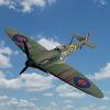
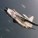
PK553 of No. 607 (County of Durham) Squadron, Royal Auxiliary Air Force, RAF Ouston, 1948. From the Airfix website: Spitfire PK553 was produced at the Castle Bromwich factory as part of contract B981687/39 and issued to No.607 Squadron, Royal Auxiliary Air Force. The RAuxAF was a force of paid volunteers who acted as a reinforcement reserve force for the Royal Air Force, giving up their evenings, weekends and holidays to train and serve in this essential force, following the end of the Second World War. RAF No 607 Squadron reformed on 10th May 1946 as a RAuxAF day fighter squadron at Ouston, in Northumberland, initially flying the Spitfire Mk.XIV and later the Mk.22, before eventually entering the jet age with the de Havilland Vampire. This was my build for the Spitfire/Seafire STGB. I originally bought the kit for £6.99 from a toyshop when I was in there and just wanted to buy a kit. If it hadn't been for me not having much time for the Spitfire GB, I probably wouldn't have made it for quite a while yet. When I saw the box in the stash I thought it would be a suitable kit - in that it would be very quick to build. But, when I opened the box, I realised I had forgotten that I had bought the Eduard etch set for it. This would obviously make it longer to build but I decided to go for it anyway - and I'm glad I did. I actually enjoyed the build despite a few 'operator error' issues!! I can certainly recommend it as a nice, cheap kit. I did originally plan on making it as the aircraft that took part in the Cooper Trophy Air Race in 1948. However, when I started looking online for information about it, I realised that most of the models from this kit were based on that version (with the big, white number 4s and red tailband) with others based on the all over silver version, from 603 Squadron. The silver version was going to be a lot harder for me to do as a brush painter but, luckily, Airfix does provide the decals in the box to make the 'vanilla' version of the aircraft which took part in the Cooper Air Race aircraft - I presume pre-race. I rather liked the idea of doing the less popular version. The photos of it can be found below. The WIP can be found: HERE Kit: Airfix A02033 1/72 Supermarine Spitfire F Mk.22 Extras: Eduard 73436 Photoetch set Paints: Humbrol, Revell, Citadel, Railmatch acrylics all applied by brush Hopefully you will be able to see some of the cockpit detail here - it's not easy to see into a 1/72 cockpit with an iPad camera! Same views as the first ones above, but with the Spitfire on my Spitfire display base. I also used a small cut-off section of slabbed area, from a previous base I had made, for it to sit on The background is a copyright free photo I found a long time ago on the internet. I really enjoy working on the cockpits of aircraft, but of course, a lot of the work gets hidden inside the fuselage once the model is complete. So here are a few photos of the cockpit before it was sealed away: A few in black and white: Thank you to everyone who commented and offered suggestions in my build thread. Thanks also to Patrice @TEMPESTMK5 for hosting the STGB so well. Comments and suggestions welcome. Kind regards, Stix31 points
-
Airfix 1/72 Whitley GR MkII in Coastal Command colours, reptesenting an airframe from St Eval, Cornwall in 1942. Out of the box with the exception of Xtradecals to represent a locally based aircraft. One of, if not the best fitting kits I've ever made. The white was a pain to spray, but a learning curve and the results were better than I have done on previous Coastal Command builds.31 points
-
Hi there I think I have learnt to load up pictures, here is my 1/72 Airfix Concorde I built a few years ago. This kit helps you put into use the modelling skills you have learned over the years, it is one of those that needs a lot of time and patience to make it look good. Here is a list of the changes made to the kit starting from the nose. Please note, this is not the build sequence. 1. Nose probe replaced with Master Mirage brass probe. 2. Nose cone external profile rounded off to remove prominent external angled ridge. 3. Internal support made for visor to reduce rake angle as the Airfix design is too flat when the nose is up. 4. Scratch built panel underneath the visor. 5. Visor back edges reshaped to allow steeper angle. 6. Fit the nose, then the visor and fill with scrap plastic and filler at the bottom of the visor to blend in. 7. Glue the left fuselage nose section to the left centre section. Repeat for right. This is done after the mating surfaces have been fettled to ensure no steps when glued. 8. Fill in all recessed panel lines and the side windows. Use white Milliput and not grey like I did, it took loads of primer to cover the filled grey lines. 9. Move the nose wheel well forward, I seem to remeber about at least 1/2’’. 10. File off the longitudinal ridges around the cockpit as the profile is over pronounced in the kit. 11. Glue fuselage front sections together. 12. Add support sections of plastic card along edges to support the wings to improve the bond and reduce the gap. 13. Glue top half of each wing to the fuselage. 14. Make up wing underside to the wings. 15. Remove height from the rear of the engine housings. This will ensure that there is no step at the wing upper surface/ engine interface. 16. Glue tail sections of fuselage together. 17. Partially cut off fin and re-align as it is twisted in plan view and canted over to one side from the moulds. 18. Glue the tail to the fuselage and use lots of plastic card and filler to blend in. 19. Replace kit wheels with Airwaves resin set. 20. Something I forgot earlier was the Drawdecal Concorde windows and door surround decals were also used here. Onto the pictures With the Wright Flyer from the AIMS brass kit The reprofiled nose and visor from 2 sides30 points
-
1/72 "Lift Here" Resin Indian Navy, Shorts SA 6 Sealand, Cochin 1953. The Shorts Sealand has a special place in the heart of Indian Naval Aviation. The type was the first aircraft to be inducted after the establishment of the Directorate of Naval Aviation and training of Indian Naval Aviators. An order for ten of these amphibians was placed in 1952. The first Sealand INS-101 was handed over on 13 Jan 53 . The aircraft arrived in due course of time by February . The last of the Sealands arrived in Oct 53. The FRU, or the Fleet Requirements Unit was commissioned on 11 Mar 53 on the Sealand under the command of Lt Cdr YN Singh who had flown Martlets with the RN off Malaya.. The FRU used to operated from Cochin's airfield at Willingdon Island, then known as INS Vendurthy II which was soon rechristened as INS Garuda. The Sealand was in service for ten years until 1963, when it was phased out as new aircraft were inducted in service. The aircraft was phased out in 1965, after just over 12 years of service. Today a lone Sealand IN-106 survives and is on display at the Naval Aviation Museum, Goa . Fairly easy kit with huge detail but needs careful alignment of wing, engines and empennage. Windows are Testors clear glue. Decals are Bright Spark and Spares. The diorama is the kit box inverted on a picture frame with a printed tarmac and hand-painted sea wall. the sea is tissue crumpled and stuck with water and glue. then painted and layered with Future and then added with random stones and wood from the garden.26 points
-
Next one done - here's my 1/144 EC-24A. Build thread is here thanks for looking Julian20 points
-
USS Los Angeles Class Flight I (688) - Riich Models [1/350] WIP: If you are interested to Flickr Album click here19 points
-
Hi fellow modelers, This topic is about my latest project in progress, the Modelsvit 1:72 Antonov 225 Mriya. Enjoy! On april 3th 2020 it finally arrived, my dream kit I was waiting for.. A 1:72 scale An-225!! Carefully wrapped and packaged for transport from Ukraine: As you see, a lot of content in the box... 975 parts in total, with PE set and mask, and 4 decal options. The first thing I just wanted to see was the size when finished , so a quick dry fit was done: Length: 1.17 meters width: 1.22 meters weight: 2.5 kilogrammes. I also have the Modelsvit 1:72 Antonov 124, a project on hold now I have the 225 kit. The 124 is the 'little' brother of the Mriya. Here you see them side by side.. I also have the Amodel 1:72 Buran kit, the Russian Space Shuttle for which the 225 was specially designed. It was meant to ride 'piggyback' on the 225 for transport, just as the Boeing 747-123 SCA (Shuttle Carrier Aircraft). (I'm also building a 1:72 B747 SCA with Space Shuttle, a project on hold, but I will add that topic on Britmodeller some time ). I could place the Buran on the 225, then it would look like the Mriya on display in the late eighties: And this is what my model would look like: Look at the 1:72 scale figure... This will be REALLY huge! The problem is, I really like the modern An-225 with yellow and blue striping. I'm still doubting which version I'm going to build.. Well, first I need to start building this kit, time enough to make the ultimate decision which version it will be. I started with the tail. As the fuselage and wings are made of fiberglass with a thin polyester coating, it's kind of difficult to work with. So sanding the surfaces to be glued rough, and use superglue or 2 components glue for the different materials used in this kit. The tail was a bit tricky, as there is a difficult dihedral angle in the tail of the 225: Then I started attaching the 'bumps' on the fuselage. Quite a lot of them: I didn't attached the biggest bumps yet, as they partially cover the wings which are detachable. So to avoid breaking loose again during a test fit, I'll wait with the attachment on the fuselage: A 1:72 Piper Cub for scale comparison.. Look at the massive size of the stabilo: The tail has 2 large aerodynamic cones attached to the rear, so I glued those parts to the tail but didn't fit at all.. Be warned, as you will notice during this project, literally EVERY part of this kit has to be sanded to shape. Modelsvit kits are not for the 'easy-builders', you need to do a lot of scratchbuilding and improvising to get things done.. These are the cones: The fiberglass under the polyester layer becomes clear after sanding One thing I noticed during the very first dry fit, was that one of the 2 provided aluminium tubes (used for sturdy but detachable wings on this model) had a wrong diameter. As you see, in the manual it says 5mm and 8mm diameter: The 8mm fits like a glove: But the 5mm doesn't fit: After checking: ..it needs to be 6mm. The problem with this fiberglass-polyester coated material that it is really hard t cut or drill; it is very brittle so widening this hole with a drill is risky.. I screwed up a little on my Modelvit An-124 model with cutting a piece, the material just 'shattered' during cutting. So as this hole is very important for a 'glove-like' fit (it has to support a large wing with 3 engines!) I will look for a 5mm diameter tube as replacement. The kit comes with a little PE set, consisting of little vents to be placed over the fuselage: Also, the fuselage has a sharp hardened edge over the entire length. So that needs to be sanded carefully: Now a little side jump. I started my 1:72 An-124 a couple months ago, but that's a project on hold at the moment as I want to finish the 225 first. From the 124 kit I already finished the nose with cockpit section; that was a project on it's own as nothing fits inside the fiberglass nose! It's a matter of constructing the polystyrene flightdeck parts together (sanding every part and filling of gaps of course): And then just 'glue the flightdeck somewhere in the nose' or something like that : ( .. No prefabricated inserts or points to attach to: So I thought first: I'm going to use my finished An-124 nose on the 225 kit, as both have identical nose shape and it saves time.. (I'm going to post my An-124 topic here some time, promised, but here a very short side jump of the construction of the 124 nose). First I glued the transparent upper part to the nose section: And here you see the constructed flightdeck, attached to a scratchbuilt support fuselage-rib, and the attached nose weight for a sturdy construction of the flightdeck to the nose. Yes, be prepared to improvise and adapt with this kit! Ok, a little more explanation. Here you see the 2 noses. Left the 124-one, right the 225-one. As you see, I fabricated a supporting rib from Plasticard. This rib 'fills up' the empty nose and provides support for the attachment of the flightdeck. This way it is possible to safely attach the flightdeck into the hollow nose, because should you 'bump' the kit to something after glueing the nose to the fuselage, and the flightdeck should come loose... you never can repair or attach it again. Also, this rib provides sturdy and secure support for the heavy nose weight these kits need to have as these kits are potential tail-sitters. This is the flightdeck: I need to blend the rib with parts of the flightdeck to make it 1 smooth construction. In this case, I replaced the curtains-parts by drawing the contours on the rib and cut it to the same shape: Measuring the width of the front flightdeck, so it can fit through the rib: This is how it will look: After cutting the contours of the curtains and fitting the flight deck through the rib, this is the result: But I engaged some fitting problems afterwards with the flightdeck, so I let it be for the moment. So I started the construction of the engines.. 6 in total. 6 Little projects, as there are quite a few parts: For every part you need to remove edges, and sand them smooth first. For example: I sprayed the turbine blades parts polished steel: And here I made a mistake.... Due to an error in the manual! It shows an incorrect drawing of fan blades attachment, so I need to glue 1 part upside down to avoid too much distance between the 2 fan blades parts. It's a little difficult to explain, but it needs to be said that this is a careless mistake from Modelsvit. Also because it's not clear how the parts finally look after glueing them. Well, lesson learned: more dry fitting with the rest of the parts first! The 2 fan blades parts are supposed to fit into each other so the 2x16 fans have to shape into 1 ‘disc’ of 32 fan blades..?? It’s clearly that that is not possible... whatever I try; upside down... ...it keeps consisting of 2 parts stacked on each other. This is how it's supposed to look: So I did it my way. The manual is just wrong. First I cut of each blade of 1 of the 2 fan blade parts and I glued each fanblade between the other part’s fan blades. I used a circular mold to keep a steady circle as the little fan blades are bended and need to be glued at an inclined angle: Almost finished... And there it is, a perfect 32 bladed fan. Now 5x16 more blades to go.. ...but job done, and ready to continue the build. So be warned, don’t glue something from this kit before test fitting it and think in advance what the result will be. Continuing the engine project, first a lot of sanding and test fitting before painting and gluing. Some parts are quite a challenge: And surprising, the engine halves don't fit at all. So sanding again... The turbine parts: The exhaust cones need to be drilled open: during the build, I made a bigger shelf to the wall as this behemoth needs a place to sit later. The shelf is 2.50 meters long and 60 centimeters deep.. ...and guess what.. still needs to be deeper, I think 70 cm: Well, first continue the build. I still got time enough left to think about another shelf. After research on the Internet I found out that the 225 engines are quite 'clean' and maintained from the inside, I saw a lot of white inner plating. So I decided to do that instead of 'gunmetal' inner halves as the (wrong) manual says: Added just a little weathering of panel lines, you don't see much left later on as the halves are glued together: And, the intake ring and exhaust cone need a lot of sanding as they do not fit well. still a lot of work to be done to these engines : ( To be continued....18 points
-
I just finished this for a GB on another site. Largely 3-D printed, with the front 2/3 of the upper fuselage coming from the Hasegawa F-117 kit. Vacuformed canopy and landing gear are from a 1:72 F-14.18 points
-
Hi all I hope you’re all keeping well? I thought I’d show you the latest model that has been keeping me amused through lockdown. It’s the Anigrand Craftworks 1/72nd scale Martin 130 Flying Boat. As usual with Anigrand kits it was not an easy build. Paints were from Xtracolor. Best regards to all, Rob18 points
-
Hi folk's a trip down memory lane now when the Beatles were still together,Adam West was Batman and we used to buy a kit at 10am and it was on the windowsill or hanging from the ceiling by 12.Mine always sat on it's stand as drawing pins all over the ceiling was a no no,built for the Kit you built as a kid GB brush painted only crap decal's and a need to raid the spares spoiled the fun a bit.Thanks for looking in.17 points
-
Thanks Bill Yes! I need reading glasses and some for the screen and some for modelling and some for close up and… Do you think they don't work? Rats Thanks Ben - they should market that again! I for one could do with a good cut! Well, now then. I wanted to see if my re-sanding had removed those nasty bits. So 'a revealing coat' I thought, that's what others do. So I brushed some DG on the sanded bits and, before I know it, this happened: Can I airbrush tiny areas like Cookie and Jamie? Should I do more brush coats like Heather and Adrian and others? Can I get variation in the brush coat like I can with the airbrush? These and other questions will be answered in our next episode… I hope.17 points
-
Airfix 1/48 De Havilland Sea Vixen FAW.2 from HMS Victorious circa 1966. Build thread is here Extras used include Eduard cockpit etch and ladder, also Reskit rocket launchers (as I'd previously used the ones in the kit for my Colonial Navy Phantom. Unless I decide to enter the Battle of Britain group build I've now go time to do my own KUTA on some part finished build before September and the MTO and Tornado builds. Mike15 points
-
Thanks Pete. I'm sure one way or another I'll manage. I'm trying printing a section off today at different settings to see what happens. Curses! You made me go and buy one. In these days of Covidity, Amazon is becoming more of an addition Those are very kind words and I really do appreciate each and every one of them. It makes the build process easier during the hard times when you know people are out there cheering you on. Today's update may get quite long and there's a very good chance I am going to be jumping around all over the place - I've been working from one end to the other this week and also getting some of those "have to do before you can move on" jobs out of the way. Life sort of began this week with an oopsie. Bummer. My plan was to have one door closed and one door open on each side so that you can see into the vestibule at each end. When I picked up the door I realized I had glued the handle on the wrong side of the door - so, off it had to come - thankfully with only minimal damage. I still have plenty of the transfers left so a small patch repair was applied. Then I realized I had ran out of the door handles I had printed at Shapeways so long, long ago. Now, a year ago that would have been a major issue but now, I can just throw the model into the printer and have at it and an hour later I have more handles than I know what to do with. Honestly! I have no idea why I printed so many when I only needed about three. Senility eh? Here's a quick comparison of my home brewed handles versus the Shapeways expensive option. Can you tell which is which? Actually, the home brew is on the left. It could be argues that the home brew is lacking a smidgen of detail that the Shapeways version has, but that could well have been my printer setting - and my FEP film was getting a bit battered and needed to be changed out. But hey - if you can tell those apart from a foot away then you're a better man than I. Handles were duly glued in place - this time double checking I was applying them to the correct side for the door opening. After that, I had to shape the interior paneling. Surprisingly I got a decent fit at the first attempts on each doorway. complete with rebate for the door to close up against. Not that anybody will ever notice it. At long last, all, yes that's right... ALL the doors are finished, complete with hardware and ready to be hung... unless I decide to add hinges. Dammit! Hinges - I will need to add hinges to the open doors but that shouldn't be too difficult a task. At the newly fitted vestibule end, the fixed door got fitted. I do like how that all looks together. Some of that hardware was a real pig to make but it does bring it to life doesn't it? At the other end I did a quick dry fit to get a visual of how the open door scenario is going to look. Works for me it does. The hand rail on the right is a little bit out of alignment but those things are so fragile I don't want to force it and it can really only be seen from this angle. I dunno, downright sloppy workmanship eh? I guess this is really another milestone. For the first time in this build, both vestibules are fixed in place along with all the doors, or at least, two doors and two door frames. While all that kerfuffle was going on the printer was churning nicely away in the background. I kept feeding it until I had three prints ready. This time I removed 90% of the supports before the final cure, leaving only those support necessary to keep the part square while it had a sunlight bath. Things went pretty good this time with no breakage and the only damage was to the end of one of the cant rails where one of the clamps bent it over and I didn't notice until I was removing the clamps after curing. One thing I realized once I started assembling this was that I was being a tad dense in my design work. I had broken the roof structure up into 60mm long sections as that's what fits nicely on the printer. That meant that I had a lot of Tee bar sections ending in mid span and I was going to have to do a lot of joining these together to make up the full roof structure. I'm going to print off some lengths of Tee bar and some cant rail separately, that way I can end the Tee bar at the carlines, than add a small length of tee bar between the carlines. I think that will look tidier than trying to join a bunch of T's in mid span. Now, since I am going to have the entire structure open I am going to have to do something with the mess at each end - back when I started this whole adventure I never envisaged having no roof so I never really gave any thought to the internal at the top of the vestibule - the roof would have covered all that - not so now. Checking back through the drawings I found that 4 lengths of steel box section was used to strengthen the vestibule area - one of the main reasons for the rebuild and so that it would comply with (then) current crash regulations. A quick search through the brass parts drawer revealed some box section I had bought off the cuff about ten years ago - and it was the perfect dimension. Win! I cut some short lengths, glued them in place then added a small length of plastic I Beam between them. Okay, that's beginning to take shape now. That was the easy part - I then spent about thee or four days messing about with no clear idea in my head as to what I was trying to achieve. My first thoughts were to make the wooden ceiling panels and I could fit small brass light fittings to them. Then I changed my mind. Idea No 2 was to chuck the wood, and use plastic square rod to replicate the strengthening beams in the vestibule area. Then I changed my mind again. I prefer using brass if at all possible, so started all over again At this point, rather than just looking at the drawings, I actually looked at the drawings... and it all came back to me. A lot of design effort went into designing the vestibule ends to meet crash regs, and one of the things we had to do was really beef up those areas and we did that by adding more beams and shear plates to absorb any potential impact. Just above the vestibule ceiling we had beams going from the front pillars, back past the end of the side frames and extending into the first compartment from each end. Like this below. Those beams were then connected to the side-frames by a number of shear brackets to transfer the load from the vestibule to the main side frames, as well as being welded to another set of pillars coming up through the partition separating the bathroom (and kitchen at the other end) from the vestibule Unfortunately the brass sections I had available, though they were of the correct X-section dimensions, had very rounded edges that I didn't like (after I had started making up the frame.) So, I changed my mind again! This time I ended up with this That all looks a bit messy so I threw some primer on, and even with the primer it starts to look a lot more like it was actually engineered, and not just thrown together. The shear brackets I mentioned above fit between the outer section and the cant rail - the small white bit that you can hardly see here below. There are three shear brackets on each beam so I have to make 12 of these little buggers when the time comes. It's going to be quite an interesting challenge when it comes time to fit this all together as I can't fit those shear brackets just now as they need to fit inside the cant rail, so I'll need to wait until the roof structure is in place before the fun and games begins. At some point during all this melee the partition got fitted between the bathroom and the dinette, along with the small plain cornicing. It's amazing the difference those last strips make to the overall appearance. The cistern got fitted. Then I had a realization... The bathroom ceiling can not be arched as in the rest of the car due to those honking great beams passing through. The bathroom ceiling either has to be flat - or it has a step to hide those beams from the interior. As I left the company in the final week or two of the build, I never got to see it fully fitted out, and there are no photo's to my knowledge of the interior of the bathroom - or at least I don't frequent those particular websites that would! That left me with a problem - the cistern pipework. That probably wouldn't exit into the bulkhead as I've shown but since it's above the ceiling it would just carry on and route to wherever it needs to go. Then an unlikely sensible portion of my brain kicked in - the cistern was not functional. We only included it because it was on the original car and it looked cool so we had it cleaned and refitted it. That being the case, the pipework would more than likely just disappear into the ceiling and end there as the ends would be hidden. Though that would be accurate I think it would look untidy so I've chosen to stick with my version. Sorted. So while it may not be 100% accurate, it is reasonably close. Disaster averted we moved on down the car. Probably 4 or 5 years after it was originally made, the dinette/corridor partition was fitted and that meant that I could now fit the cornicing around the dinette. What a difference instead of hang those raw edges exposed at the ceiling level. as a quick comparison, the bar side is still "unfinished" while the dining room side has the cornicing fitted. - Though not without some issues of my own making. I hadn't really paid close enough attention to the height of the cover strips and they weren't all equal. Yeah I know - sloppy workmanship yet again. That meant in order to prevent the cornicing wandering all over the place I had to trim the tops of the cover strips so the alignment was reasonably horizontal. A brand new sharp chisel blade came in very handy here to remove the high offenders and even up the top level. While I was traversing up and down the car, I remembered to fit the last three hand rails - the three chromed rails in the bar area. The drunkards can be herded safely now. I also started on more ceiling partitions - this time the dinette/dining area partition. The hole in the center is for the ventilation - coming soon to an exciting episode near you. There's been a bit of discussion here and there about white versus red oxide and which would be best. My gut instinct was to stick with red oxide as that would be be more realistic and actually reflect the real build. Well, during the week, a small jar of red oxide magically appeared. How as it going to look? Judge for yourself... ( beams just dry fitted) Personally, I think it looks great. It's not too bright and in a remarkable stroke of luck, it does seem to go with the overall color scheme, blending in very nicely. So while the airbrush was fired up I slapped some paint on a couple of roof structure segments. I'm liking this red oxide finish. - it really looks the part. The big question though is: How does it affect the overall visual when trying to look at the interior? As far as I can tell, it's gong to be absolutely fine. This shot is digitally untouched and all the color hues are very similar yet you can still clearly see inside without being distracted by the framework. I did adjust brightness and contrast on this one, but threw a table in there just to see what the effect was like. I firmly believe that once the tables and chairs and other assorted gubbinses (i.e. lamps) are in place, you will hardly notice the roof structure. wow. This has been a bit of a mammoth post so I guess it's time to leave and get some more coffee. I'll leave you with a couple of parting shots of where we stand now I find this shot strangely comforting okay. I'm finished - yes really. I am. The printer is finishing up another print and I want to see how it turned out since I went a bit crazy with the exposure times for a small experiment. toodle pip chaps15 points
-
1/72 TRUMPETER SU-33 RUSSIAN NAVY15 points
-
Kit: 1/72 Airfix BAE Systems Airfix Hawk T1A Red Arrows Subject: BAE Systems Hawk Mk T.1.A XX240/849, 736 Naval Air Squadron, Royal Navy, RNAS Culdrose, 2014 Details: Modelled as per reference pics from interweb Misc: Hataka Orange line paints, Humbrol paints, Oils. Xtradecal 72230 and Xtradecal 72168 stencils Thanks for looking15 points
-
Kit: 1/72 Tamiya F-4S Phantom Subject: F-4S Phantom 153904/106, VF-301 Devil's Disciples, US Navy, NAS Mirimar, CA, USA 1984 Details: Modelled as per reference pics from interweb Misc: Hataka Orange line paints, Humbrol paints, Oils WIP Link: Here Thanks for looking!15 points
-
Holt 150 ton Field monitor Let me introduce my entirely 1/48 scratch-built whopper – the Holt 150 ton Field monitor. During the Mexican boarder war (or was it the Mexican revolution – it's so bloody confusing) the Americans seriously considered building these monstrosities, and arming them with two 6” naval guns. It seems the main reason they decided not to, is because the metal monsters wouldn't be able to keep up with the cavalry horses. There are no contemporary pictures or diagrams and only a pretty confusing written description, from which a modern side view has been cobbled together (see WIP thread). My model is mainly (but not slavishly) based on these. I've had a stern word with my camera ( words like “get a grip” and “snap out of it” were used) and managed to get some pics. As I said in the WIP, I'm aware the base looks more like Blackpool beach than the Mexican desert and I know it's a bit of a let down that it isn't displayed as a Whopper versus Mexican donkey stare-off, but hope you like it anyway. Thanks for having a ganders. This is the work in progress, although at 17,000 words you may need to wait until you retire before you tackle it.14 points
-
Pretty much trouble free build but the wide yellow wing/fuselage decals were quite thick and required lots of micro sol/set. I've never seen so many decals on a plane before! Eduard masks for Canopy,ultimate grey primer, followed by Vallejo model air metallic and a top coat of Alclad Aqua Gloss.13 points
-
Thanks Cookie, kind as always Suspense over, I decided on brushing with thinned paint, if only because I was more confident that I could do both colours in the same session. Does that make sense? Thanks Rob I think I'm getting the hang of it - thinned coats are the answer to getting a variation as you say, with Micromesh to 'correct' any heavy-handedness. Another coat: Legs and prop painted too. Aerial stuck in so I can knock it off again - isn't that an essential part of the build?13 points
-
1/72 Airfix Supermarine Spitfire F Mk.22 PK553 of No. 607 (County of Durham) Squadron Royal Auxiliary Air Force, RAF Ouston, 1948. The WIP can be found: HERE The RFI photos can be found: HERE Kit: Airfix A02033 1/72 Supermarine Spitfire F Mk.22 Extras: Eduard 73436 Photoetch set Paints: Humbrol, Revell, Citadel, Railmatch acrylics all applied by brush13 points
-
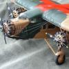
USN F2A-2 Of VF-3 Circa 1941 USS Saratoga Here is my finished build, using the Tamiya kit. Really enjoyed building this model, the paint job lets it down a tad but hey I finished a Model Thanks for looking in Build Log can be found here Photos13 points
-
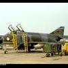
RA-5C Vigilante BuNo156633/NK603 of RVAH-13, USS Enterprise, Operation Linebacker II, December 1972 The last of the Vigilantes to be lost in the Vietnam war. It was hit by 'Atoll' missile fired by MiG-21 - unfortunately killing the navigator and pilot becoming a POW. This was in fact the only Vigilante lost in aerial combat. Kit: Trumpeter RA-5C Vigilante (#01616) Scale: 1/72 Aftermarket: Eduard Photo Etch, Master pitot tube, Print Scale decals Paints: Vallejo Model Color, Model Air & Metal Color Weathering: Flory Models Wash, Mig weathering products Mixed feelings about this kit - but it's (more or less) a Vigilante, so that's cool Build thread:13 points
-
The Tamiya's P-47 kit is one of my favorite kits. This kit was painted with AK interactive RAF camo set. I used Tamiya clear weathered with masters touch oil paint and Tamiya clear flat. The decals are from Xtradecal.12 points
-
Hi folks My latest build is an F-5B in 1/48 scale from Kinetic. -The kit shape is good but to me it was a little challenging in some parts. -Colors are Hataka and Gunze painted free-hand. -Decals are from Print Scale. -Resin ejection seats are from Wolfpack Design This aircraft entered in service with the Imperial Iranian Air Force in mid 1960's and the IIAF became the first Air Force to receive Freedom Fighters. The two-seaters were in high demand in order to train new pilots locally. Hope you enjoy Barzin 2020_06_14_IMG_8080 by Freddy Pilot, on Flickr 2020_06_14_IMG_8072 by Freddy Pilot, on Flickr 2020_06_14_IMG_8073 by Freddy Pilot, on Flickr 2020_06_14_IMG_8081 by Freddy Pilot, on Flickr 2020_06_14_IMG_8090 by Freddy Pilot, on Flickr 2020_06_14_IMG_8092 by Freddy Pilot, on Flickr 2020_06_14_IMG_8095 by Freddy Pilot, on Flickr 2020_06_14_IMG_8097 by Freddy Pilot, on Flickr 2020_06_14_IMG_8083-1 by Freddy Pilot, on Flickr Last Iranian two-seater Freedom Fighter produced, 01613, at Ramstein (Germany) on 12-06-71 still in USAF markings. photo_2019-08-20_19-42-00 by Freddy Pilot, on Flickr IIAFF-5B2-328_jpg by Freddy Pilot, on Flickr IMG_0214 by Freddy Pilot, on Flickr12 points
-
Here's the second of my 1/144 USN FEWSG pair - the NKC-135A. Build thread is here thanks for looking Julian12 points
-
G'day Chums,for your delectation I present my 1/48th scale ICM FR IX. The build thread is here.Thanks for looking in.12 points
-
Type VII C/41 U-Boat U998 1943 Here is my entry to the GB; Revell's 1/144 U-Boat. I was quite impressed with this kit, it went together very well with generally good fit, some of the finer parts were difficult to get off the sprues without damage and indeed some were already broken in situ. Built out of the box. All great fun for me especially as it gave me the opportunity to build outside of my normal sphere of interest and to really go to town on some weathering. Thanks once again to the Host, co-hosts and the other participants. Cheers, Mark.12 points
-
Here's my 1/144 EC-24A, built for the In The Navy group build. The EC-24A was a DC-8-55 converted for use by the US Navy Fleet Electronic Warfare Support Group as an electronic aggressor. It's the Minicraft kit with shortened fuselage, Bra.Z resin engines, and scratch-built conversion parts (mostly 3D-printed). Decals are from various sources, including some I printed myself. Build thread is here. thanks for looking Julian11 points
-
Hi, This is what is said already in topic name: a scratch conversion of Airfix (1/72) Sunderland III using @AdrianMF home made vacu fuselage and Red Roo Models conversion set for RAAF military Empire (dedicated originally to CMR resin kit). The WIP thread is here: The model presents Short Empire S.33 A18-14 (No S.1025) somewhere between April and August 1942, when she wore already "red free" style of RAAF roundels but still have installed armament and served wit 33 Squadron RAAF in Townsville. Here she is: The most characteristic bull nose of Empire On shelve with her sistership - the Sunderland Again many thanks for AndrianMF gift of his jome made vacu fuselage and for really great support with photos, infos and RedRoo conversion set from EdRussell. One can say that the model has three fathers, but what then to say about its mother? ... Comments welcome Regards Jerzy-Wojtek11 points
-
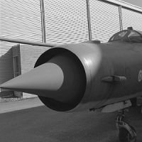
Sunday morning and the sun has returned after sseveral days of November-like darkness and rain. 🌞 This post is bought to you in connjunction with the 1970 Genesis album Trespass and today's nut is the walnut. Well, it seems to have just been one of those weeks you creep through with everything seeming to take an enormous effort to accomplish even the most minor of things. Notwithstanding this, there is some minor progress, a bit of research, and a couple of decisions to relate but first, the to the reading of some telegrams: Flickr's new 'suspense' algorithm at work I see. Reckon I'll stick with 2 from now on as well Alan, given the lack of discernables. Both good points to bear in mind on the exposure/height relationship. The very finest 'whisker' (0.2mm) did indeed print but suffered subsequently in the IPA bath, so it's reasonable to suppose that a longer exposure may indeed mitigate this sort of thing. That said, anything at that diameter I'm most likely going to resort to brass or wire for anyway. The 0.2mm wall remains nicely intact however and has hardened to what I'd describe as thin card. The region that caused me most anxiety in the early days was the trailing ege of the wings where they meet at a point but I have to say that they've behaved themselves impeccably - even the rearmost part of the root where it flares out to merge with the side of the engine bay looks nice and sharp, with no hint of erosion from the IPA. .....deletes image to mess with audience expectation.... I'm not an unreasonable man Giorgio. We'd meet halfway of course - in dirigibles! Ye Boneyarde: Some research and decisions then. In terms of bulging and recessing various parts of the underside, a graphic of the main areas for attention that I deliberately left the front wheel well out of honest... 😁 Those who've endured my ravings on previous builds will know that each project for me is a combination of learning new skills and trying to do something with the subject that hasn't been done before, so in terms of treatment of the subject here, my main interest (aside from threshing towards some kind of acceptable shape at this scale) remains the engines, radar and RAT. It's easy to get distracted from these goals by all the other appealing features of this aircraft but stwo features I've decided to forgo any serious internal detailing of are a) the airbrake (with the Pavla/Eduard stuff used on the Airfix 1/48 there's already many nice builds showing this feature to good effect) and b) the flaps - largely because the only shots of Vixens on the ground with them drooping to reveal their innards are museum ones - operational ones I've not seen lowered at all, (open to correction on this as alway). That said, there is the bulge of the airbrake needing representing and this had me poring over reference shots for quite a while: The bulge itself is apparent but - as with many things Vixenish - contains ambiguities that need close scrutiny. The bulge begins just aft of the bulges for the Microcell rockets and is quite apparent in many shots, however the extent of the bulge where it returns to the fuselage shape is not quite so easy to discern. In many side views it's obscured either by the ventral strakes on the airbrake itself, or by fuel tank/pylons. James and myself pored over images of this area on Zoom the other week looking at just these self-same areas. Initally I was convinced that the bulge almost-imperceptibly faired-in to the fuselage again at a level just in front of the wheel wells however, after hours sifting through visual refs from different angles and in different lighting conditions, I don't think it extends back as far as that, but terminates at the rear of the airbrake opening. Some contrast-stretched and enhanced examples of this: Image credit: (again my obligatory apologies to these photographers for not having a record of provenance to credit you with - -happy to correct this if you get in touch) You need to be real careful with oblique lighting conditions of course because they exagegerate relief but I think the fall of shadow at the rear of the airbrake opening in the above images is pretty conclusive regarding the defined change in curvature. Few profile shots delineate this clearly but this lovely one from @Julien in the FAW.1 walkaround on the forum here lets you trace the contour transition immediately behind the airbake strake: It's subtle enough that in many lights (especially under diffuse or shaded underside illumination) this the discontinuity disappears so that that the bulge just seems to blend in to the belly farther back. Hopefully I've managed to catch something of these appearances here (bear in mind there's another smaller bulge yet to add on to the airbake bulge itself (that accommdates the mounting of the hydraulic ram) which will also alter visual perception of the area later: Seen from the front in many photographs, it's suprising just how much the initial front rise of the bulge seems to recede into the airframe - again, a balancing act between subtelty and presence that I hope works here: The baroque shape of the airbrake opening itself will be added - along with many of those for access panels &etc. at the painting stage - not as recessed panel lines - due to their fineness at this scale. This morning I also completed minstration to the tailplane structure: Hinges/linkages are different top and bottom, with the ones above having clearly visible negative openings on either side of the hinges. Underside of same: Those five slots are recessed at about 0.2mm at max. depth so I'm hopeful at the print stage these should have an acceptable 'just-about-visible-ness' in terms of surface relief: Elevator and hinges/recesses: One final piece of research to note in respect to XJ481 is that aside from the modified Martel nose tip, there is visible in this shot and opening in the port lower quarter for purposes unknown: Scratching my head trying to think what would need to point downward and off-axis like that during the missile tests. Complicated by the fact that whatever was installed for the tests appears to hacve been removed by the time the photo was taken. More during the week I hope. Tony11 points
-
Here's my final contribution - the Brazilian Navy AF-1A Skyhawk. Build thread is here thanks for looking Julian11 points
-
Thanks Keith The final 'full brush' coat has been applied: I'll let that dry properly (honestly, this time) then take the underside mask off and use Bill's 'dot painting' technique for any problems. Micromeshing and pre-transfer gloss coat to follow.11 points
-
So, this happened.11 points
-
Hi @giemme, @Edge, @Bill Livingston and @JosephLalor. Hope you are all well. Thank you very much for your kind comments. Well, over the weekend I managed to get this finished and I'm actually quite happy with the result. I have thoroughly enjoyed making it and I can certainly recommend this rather nice, cheap kit. The PE adds something but I don't think would be absolutely necessary to make a rather good looking Spitfire. Thank you too to everyone who has commented and offered help during the build and to @TEMPESTMK5 for his excellent GB hosting skills. I'm off to build a tank for a bit and then I'm hoping to be building a Hurricane in the Battle of Britain GB. A few photos of the finished Spitfire here: A LOT more photos can be found in the RFI section here: https://www.britmodeller.com/forums/index.php?/topic/235075103-172-airfix-supermarine-spitfire-f-mk22-eduard-pe-set/ The Gallery photos can be found here: https://www.britmodeller.com/forums/index.php?/topic/235070462-spitfire-stgb-gallery/&do=findComment&comment=3724198 Comments and suggestions welcome. Kind regards, Stix11 points
-
Eduard 1/48 Profipack Spitfire mk.VIII MD280 of 155 Squadron in Burma. Hi all, I finally finished the last bits of the build. As always a lovely kit from Eduard, that almost clicks together. If you wonder why the lighting for the overhead shot differs from the others, I couldn’t possibly admit that the cowling joint was showing in overhead sun - in any normal lighting it’s perfect, so that shot was when it clouded over. Cheers Will10 points
-
Hi Everybody, this is my second lockdown build and another Russian jet. A very enjoyable build which went together well with, the exception of the undercarriage doors, I suppose with the wheels down all they have to do is represent the doors. Build them in the closed position and they are not even close. Built straight out of the box and painted with Tamiya acrylics. I would be the first to admit this is not one of my better builds, so comments and criticisms are welcome. Thanks for looking, stay safe everyone.9 points
-
This is my Sword 1/72 TBM-3W Avenger. The TBM-3W was developed as the first US Navy Airborne Early Warning (AEW) aircraft during the latter part of WW II under Project Cadillac (named after the mountain in Maine where tests were performed, not the car). While the TBM proved a little cramped for the AEW task and was superseded by variants of the Douglas AD Skyraider in that role, when teamed up with a TBM-3S it served as part of a hunter/killer team in the Anti Submarine Warfare (ASW) role for several years until replaced by the AF-2W/S. While certainly not Hasegawa this Sword kit proved to be a very pleasant build with only the wing to fuselage connection proving problematic. The slots in the fuselage for the wing tabs were a bit undersized and needed some filing and then the joint needed filling, but that is par for the course from these smaller manufacturers. The only other issue was that the otherwise excellent decals wanted to stick for dear life to the first location they were placed. I found that I could work a wet brush under them and once loosened they could be repositioned. But this also had a tendency to make the roll up into a unusable ball. Luckily I had a second set handy and it all turned out in the end. In my net searches I came across this picture of the aircraft that the decals were for So we can see how close I came. I am looking forward to Sword's upcoming release of the TBM-3S2 to build the killer half of this pair but until them next up will be the Octopus/Pavla F7F-3N Enjoy9 points
-
Good evening! There was a bit of a work in progress thread for this build a while ago. The build has been done with it for a quite a while, but I worked on some photography this afternoon. I've got to work on depth of focus and few other things on the photography, but this was my first time shooting models in a light box. It's already much better than trying to do it on kitchen counter, but I've still got some learning to do. The air data probe is just press fit on the aircraft now. That way I can remove it if necessary and it doesn't get broken off. The wingtip pitot is complete, but not installed at this time for the same reason. On to the photos! P1030509 by J Hooper, on Flickr P1030512 by J Hooper, on Flickr P1030513 by J Hooper, on Flickr P1030515 by J Hooper, on Flickr Cheers, and I hope you enjoyed! Hoops9 points
-
Good afternoon Members of the most gentle parish in the land. I hope you’re all having a splendid weekend. It’s been a busy work week but small progress has occurred over the Past few days. The holes got Added to tidied and the tubes got drilled. I made little plates for them and glued it all in place. Primer was added. Happy with that. There is a round vent that sits in the same area that didn’t exist. more holes? Well i decided to make one, the rim that is from the spares box. Cut that off. Stuck on some tea pig bag mesh. And the glued in place. If only It looked good. 🤦♂️ It looked good on the night I did it. Next day, not so much. Soooo I pulled it all off. I drilled the hole I should have drilled in the first place. Better. 😇 A small 2mm disc got punched with some tea pig mesh on it and glued in place. The tail actuator things got glued on. And the booms got sanded. I added the kit bit and made up as best I could from photos I had the detail on the rear combing. Lashings of lead wire. Glued at one end. And then tidied up. The boom protectors got cut off and made again on a better shape. And with the lights on. And that’s about it for plastic. I pottered down stairs, Gem rushed out saying she had bought me something on Facebook market place. 20 mins later and ten whole pounds lighter in the pocket we are here. Lockdown hammock!!!!! Amazing. I love that woman. ❤️ Then this flew over and I thought of you guys. 🛩 In the middle. It looked bigger in my eyes. 🤣 take care you lot. Thanks for all the comments and help with this beast of a build. Stay safe and as always, happy modelling. Johnny9 points
-
HMS Nelson 1945 Airfix 1/600 Build:9 points
-
Hi guys I have just about managed to finish the basic construction of the rear fuselage and tail section with just a few details to add at a later stage. So after this post I can get on with working on all the internal detail! So first up I had to think about how I was going to go about making the structure of the Cheyenne rear turret. After measuring up for scale from photos I got a sheet of plastic card and put together the frame work. I won't be glazing the turret or fixing it in place until all the internal detail in the turret is complete...this is because I will never get my fingers in there to do anything!.....so here is the Cheyenne turret frame work..... After fixing some sort of band of plastic around the aperture so that the frame would have something to adhere to I placed the turret in position to see what it looked like......I am happy with the out come as I thought it would give me no end of problems considering I had no scale plans to go by. Here it is in place..... So it was back to the tail section. I decided to skin this section now in preparation of spraying. Most of this B17G Fuddy Duddy I am depicting is bare metal except for the tail section where there is a splash of yellow. So first up was to mark the rivet lines with pen.... The material I am using to skin the tail is quite simply sticky back silver paper which is thinner than the aluminum skin I will and have been using for the bare metal sections.You can see in this next photo that after I traced a template the rivets were punched by my handy rivet maker tool (a safety pin inserted into a piece of plastic sprue!....no expense spared!) and its ready to be glued to the tail section.... ...and here is the tail unit skinned..... The next job was to sand down all the formers making way for all the internal detail that I will be starting on soon....this was done on both top and bottom of the fuselage half's Using some of my collection of yogurt pot plastic tubs cut to shape!.. I started on covering the internal floors and side walls... The last 3 photos are of some of the detail to the rudder... eg...the trim tab rod connection and the rudder connection fittings to the tail section... That's it for now guys. Next up is making the ribs for the floors and side walls on the lower half of the fuselage and possibly spraying the tail unit....so until then stay safe! Cheers Martin9 points
-
Remember the door vent things... Or just get on and make the things, how hard can it be? Make bubbles My workbench has several especially prepared (Much to the annoyance of s.w.w.s.w.o I might add) holes drilled partway into the melamine surface. All of different sizes or shapes, intended for this purpose. Take perfectly formed former (natch!) and make the mouldable plastic floppy over a tea light flame then plunge the tip of a perfectly engineered paintbrush onto the plastic through into the selected mould hole. Do a few then cut away all the plastic you don't need which will leave you what you need and the priceless opportunity to scrabble around on a hard composite floor looking for the second half when the required downward trim cut is made. Eventually you can then call upon the Gator's Thin to bung the half domes onto the fuselage And Well that's that. Thank you for allowing me to demonstrate the Acme Desk Hole Operation to y'all.9 points
-
Here's my 1/48 A-4C built as 147781 of VX-5 in 1965. Hasegawa kit with Two Bobs decals and a Taco resin AGM-62 Walleye cheers Julian9 points
-
Hi all, so here's my first completed kit here (and the first in ages). I was posting in-progress updates over at the WIP section of the forum and now it's time to post a couple photos of the complete thing. The base was Smer's kit. I also used Kora's resin wheels (not impressed), Brengun's photoetched parts (designed to be used with RS Models kits), Falcon's vacform canopy and Print Scale's decals (not very good). Primer used was Vellejo's grey acrylic (I'm not buying that one again), Life Color paint for the interior and Hataka's WW2 French air force paint set for the camo. Gloss coat was Future/Pledge and matt coat was Windsor & Newton's UV matt clear varnish. Weathering was done with Humbrol's enamel wash, Vallejo's acrylic wash and Talens oil paints. In fact I'm so optimistic more will follow, I even got me an IKEA show case. I plead guilty to all charges against me. I have committed all conceivable crimes against our hobby. To my defence, almost all techniques and material used here I have done for the first time. I have learned a great deal off from this project. Would love to hear what you think. Thanks for looking.8 points
-
Here is my latest kit finished during this week. It's Miniwing's 1:144 Dornier Do 18G-1. It represents K6+CL of 3./Kü.Fl.Gr. (Küstenfliegergruppe) 406, Luftwaffe, in 1940. This resin kit with vacform transparencies gave quite a bit of work. Some corrections had to be made like the top of the nose section as it is too high and curves up to the cockpit in profile when it should be lower and flat. The kit only came with one water rudder when the plane had two so I made a couple from plastic card. All masts, antennae, wires and rigging was made from stretched sprue. The kit was fully painted and varnished with brush. I had to overpaint some of the decals as the printing and or colour was poor. I scratchbuilt a beaching trolley using various builds of the Matchbox 1:72 kit with the Kora resin trolley kit as a guide. It was loosely based on this and although I made a mistake and it came out longer than it should be, I'm very pleased with it. It was fun!! As the kit was tail-heavy, I had to glue the trolley to a home-made base and the plane to the trolley. Despite some frustrations (and procrastinating) it all paid off and I'm very pleased with the result. Thank you for looking and all comments are welcome as always Miguel8 points
-
May I present my representation of Spitfire Mk IX MH434, one of the best known Spitfires flying today, flown for many years by the late great Ray Hanna and his son Mark and operated by The Old Flying Machine Company from Duxford. I started this build in October 2017 and used the Hasegawa kit with an Aeroclub fuselage to correct the mistakes in the kit item and an Aires cockpit set. I also used a canopy from my Spitfire canopy spares box as the kit supplied one is not ‘blown’ enough compared to that seen in photos of the aircraft after a rebuild and repaint in the 1990s. After the repaint the aircraft now carries slightly out of proportion upper wing and fuselage roundels which I have attempted to replicate. The model is brush painted with Xtracolour enamels with semi-gloss varnish sprayed on in an attempt to cover any remaining brush marks. I used the fuselage markings from the old Airfix Mk IX which led to the ‘Z’ on the port fuselage being a little too far forward and slightly overlapping the entry flap, having positioned the roundel partly over the radio compartment hatch using photos of MH434 as reference. I hope you like it. John.8 points
-
Inner calm is restored (more or less). After I spent most of the day doing something completely different, the various 'fixes' seemed to work remarkably well. The cracked wingtip failed to survive first contact with Gorilla superglue gel and rubbed down nicely. The large wing decals which I had been given (ex-Aeroclub RE8) worked like a dream on both the upper and lower wings: The fuselage codes seem to have come out okay and the aftermarket fuselage roundels gave no trouble at all: I still have to sort out the blemish on the port side of the nose, but the darker blue markings look much better than the previous versions. Victory from the jaws of defeat, and all that. Jon PS Apologies for the slightly blurred smartphone pics, which I've just noticed and must look rubbish on a PC screen.8 points
-
This is what the Vickers machine gun ‘walls’ look like as provided by Tetra, so some careful separation is going to be required It’s amazing how much time gets eaten by tiny details; what follows is 3 hours’ work. First up, as I have observed before, all this sanding and correcting detail plays havoc with the bits Merit did get right; notably the characteristic weld seams that were so prominent on / characteristic of Ark (because of the need to reduce weight because of the Washington Treaty). I have two options; resin transfers (which I will probably use on the hull) and - believe it or not - 1/350 brass weld seams provided by Admiralty Modelworks. These look great, but they are bloody hard to fit neatly, so I think these ones on the island are the only PE ones I’ll use (plus they aren’t cheap!). Not perfect, but under paint they’ll do the job in giving the casual eye the impression of lines: Next up... a while ago I built some detail to add to the inside front face of the compass platform. And then promptly lost the pieces. Yesterday I found a couple of them lurking in the bottom of a box, so decided that I’d better fit them before I lost them again; Finally for now, I have started on the crash barrier piston I discussed a couple of days ago: All pretty tiny, but together they’ll add up to added convincing detail. More soon Crisp8 points
-
USS Lexington (CV-2) Meng 'toon' style kit Build log here8 points


This leaderboard is set to London/GMT+01:00