
Leaderboard


Popular Content
Showing content with the highest reputation on 13/04/19 in all areas
-
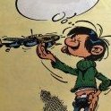
The Petlyakov Pe-2 was the Soviet light bomber used during World War II and considered as one of the best ground attack aircraft. Built over 11,000 units, it is also one of the most produced twin-engine attack aircraft. The Pe-2 was fast, maneuverable and durable and it was also successful as the roles of heavy fighter, reconnaissance and night fighter. The model replicates the aircraft flown by Senior Lieutenant E. Sedov, 40th Bomber Air Regiment, Soviet Navy Black Sea Fleet Aviation, August 1944. The kit is the Limited Edition from Eduard containing photo etch frets, resin parts and a set of canopy mask. It also includes 5 decal and paint options. It was fun building.34 points
-
Hello all, I officially finished the build of Schnaufer's 110G by taking some proper photos. Build thread here: Two noteworthy things about the build; one is that I managed to squeeze in Aires' cockpit detail set made for the Revell kit: Second, I used the AIMS update set - the main appeal is the clear resin cowls that allow you to have the transparent triangular windows. Since Schnaufer reportedly preferred machine guns over the cannons fitted to the nose, I used a machine gun nose from an Eduard 110E kit. I also used the propeller blades and some antenna from a Revell 110 kit. Painted the model mainly with MRP over a black primer base. Weathering with Vallejo and AK-interactive pigments and enamels. All sealed with Vallejo clear flat thinned with alcohol. The figures in the photos are all from ICM - which are really great. The winter base in the photos is from Noy's Miniatures. Thanks for looking! Feedback is always welcome! Elger27 points
-
I have finally got around to uploading some photos of my Boulton Paul Defiant Mk.I. I thought I had posted it last weekend before we went away for the week, only to discover today that I hadn't. So anyway, ready for inspection is my 1:72 Airfix Boulton Paul Defiant Mk.I, the aircraft is built in the night fighter scheme of N3328 of No. 151 Squadron, flown by Sgt J.L. Coulter (pilot) RAAF. There is a wealth of information about this aircraft online and film footage of the excavation of its crash site available on YouTube. I would like to thank Andy for emailing me the crash cards from the real aircraft, I aim to sit the build ontop of them once printed. The build is an out of the box build, the kit went together really well Airfix have done a fantastic job, the only variations I have made is using Vallejo acrylics, and mixing up a very dark grey/black for the aircrafts top coat. I hope I have done both the pilot and aircraft proud. Thanks for looking.24 points
-
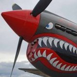
Kit markings mostly for plane #7 flown by 7th FS/49th FG ace Joel Paris. This was an on again/off again build for too many years to remember, and recently I decided I needed to actually get the thing finished. Unfortunately I waited until after all painting was done to attempt the heavy weathering and paint loss that occurred on the white leading edges, and the result was less than satisfactory. This was mainly due to my "brilliant" idea of using Tamiya white surface primer, thinking that I could kill two birds with one stone by priming the model and painting the white areas to start as well. In hindsight I should have just painted the whole wing area with the olive drab/medium green splotches on top and the neutral gray underneath, then used the 'salt method' to cause the chipping and paint loss when I then painted the white leading edges. Another shortcut I did was keeping the canopy on when I sprayed the primer in order to 'mask' the cockpit, but when I took off the canopy masks when all was said and done the white really peeped out under the olive drab. Live and learn or, as Pippin warned Frodo: "Short cuts make long delays." Here's a photo of #7 that shows the heavy weathering and/or paint loss of the white leading edges: Here we go with my model: Another photo I've seen shows what I refer to as a black 'fat gremlin' with the white numeral '7' inside it on the port wheel 'knuckle,' which I feebly tried to replicate with my shaky hands using a very fine black marker and very thin brush. I have no idea if the same was present on the other knuckle, but I figured it wouldn't hurt to put one on. Thanks for looking, and all constructive criticism and comments welcome! Cheers, Mark23 points
-
Airfix first produced the 1/48 Junkers Ju87B-2/R-2 in the 1980's this was probably from all the work they did on their 1/24 release. Unfortunately this was one of the last releases Airfix made before their 'initial' demise and the kit reflects this. Although being dimensionally correct the kit gives the appearance of almost being a 'test shot' seemingly unfinished. Maybe this was Airfix trying to survive their coming demise by releasing new kits as quickly as possible. I bought my Stuka almost as soon as it was released but it languished in my stash until now even though it was bought out occasionally and little bits of work were carried out but then went back into the ever growing stash. Move on nearly 40 years and lo and behold the re-established Airfix release a Junkers Ju87B-1 in 1/48 which I immediately added to my stash. This release is of course light years beyond the original 1980's release. I then decided to commence a dual build of the two Airfix Stukas and here I present the end results :- Below are the end results of the 'first tool' Junkers Ju87B-2 although built as the R-2 trop version. The details I added to this build were new interior using parts from the Hasegawa Ju87B and scratch, some interior parts from the new Airfix kit such as instrument panel, 'bomb aiming' window parts, flaps and ailerons. A Falcon vac form canopy was used, under wing bomb racks replaced, all rivet detail removed, panel lines re-scribed, drop tanks from Eduard. I made no attempt to correct the lack of detail under the fuselage as the bomb tends to disguise this area. I painted this kit with Mission Model paints for 70/71 upper camouflage and AK Real Colours for the 'early' 79 /65 colours. Weathering I kept to a minimum, decals sourced from my 'decal library'. This kit represents a Junkers Ju87R-2 Trop from 4./St.G2 'Immelmann' Libya, May 1941:- Now the recent Airfix Ju87B-1 this kit shows the advance in our hobby over the years, an excellent kit, detail far beyond Airfix's first Ju87B. I built this kit with cowlings off showing the engine which is well detailed but looks even better with a little extra detailing added. I used the Eduard photo etch details plus mask, Quickboost replacement prop.blades plus spinner and the Xtradecals sheet. The main criticism of this kit is the unfortunately placed injector pin marks (easily dealt with) and the exaggerated rivet detailing which I left alone. Kit was painted using the new AK Real Aircraft Colours which are a pleasure to spray with, although I feel that maybe the 70/71 colours were a little on the dark side!! I used the Xtradecals sheet which as always performed well. The kit was finished as a machine from 7./St.G51 France 1940 again weathering was kept to a minimum:- An interesting comparison build showing how our hobby has advanced over the past 40 years, or in my case the past 55+ years 😖. Cheers Andy22 points
-
21 points
-
It's the Tamiya 1/32 kit with the Eduard Brassin port engine, Xtracolor paints and Aviaeology decals. The aircraft represents one flown by Squadron Leader Vic Cherry, a Texan who flew with the RCAF's 418 Squadron.18 points
-
Hi. I have just finished build of this great aircraft. I used PE parts from Eduard (cockpit and flaps) and few spare decals. Everything other is built from scratch. It is painted with AK Interactive acrylic paints. The kit requires a lot of putty and patience, but you can build a really nice looking aircraft model from it. Have a nice day I also made a video of the build:15 points
-
My dear modeller friends, I've just finished my interpretation of the last moments of the USS Indianapolis. I bought this Tamiya waterline series kit, on an eBay's auction, a few months ago, already provided with Gold Medal photo edge parts. I kept it on my stash for future building, but, when my company sent me on vacation in this period, I couldn't resist building. My plan was to realise the USS Indianapolis last navigation's moment when she was torpedoed by the Japanese I-58 submarine. It was the 12:14 am of July 30 1945, when she was navigating in complete radio silence on the Leyte Gulf. I think everybody saw Nicolas Cage's movie, and so I think the story is quite known. For this realization, that involved the torpedo on water, I explored a new seascape building material, the epoxy resin. A material for me absolutely unknown, and for this reason, I saw a lot of tutorials on the YouTube Channel. My first attempt was using a sea blue painted wood base with a 1 cm. thick layer of light blue painted epoxy resin over. Then when the first layer was cured, I added the torpedos on place and the second thinner layer of same light blue epoxy resin. The result wasn't so bad, but I found the torpedo's shadow on the wood base very annoying. Trying to solve the problem I came up with the idea of placing the seascape on a transparent base, and, for this reason, I used a glass, lightly back painted with a different tone of blues and greens, in order to simulate the Pacific Ocean water, and the same procedure with the epoxy resin as the previous attempt. The final result it satisfies me more, and I think it is more realistic. Anyway I don't want to bother you with unwanted explications and so, this is the result, I hope I'll like it: IMG_20190413_143222 by Franco Segato, su Flickr IMG_20190413_143233 by Franco Segato, su Flickr IMG_20190413_143300 by Franco Segato, su Flickr IMG_20190413_143245 by Franco Segato, su Flickr IMG_20190413_143321 by Franco Segato, su Flickr IMG_20190413_143426 by Franco Segato, su Flickr IMG_20190413_143440 by Franco Segato, su Flickr IMG_20190413_143450 by Franco Segato, su Flickr IMG_20190413_143533 by Franco Segato, su Flickr IMG_20190413_143557 by Franco Segato, su Flickr IMG_20190413_143628 by Franco Segato, su Flickr Comments and suggestions are always very welcome: Thank you and see you soon. Happy modelling! Franco14 points
-
Hi all, this is fw 190 d-9 w. Nr 213240. Red '13' of jv 44. Flown by oblt Klaus Faber. Ainring airfield may 1945 The kit is tamiya d-9. True details wheels, Seat belts added, Streached sprue airials, and head armour support cables. Xtra color paints rlm 75, 83, 76, 04, 81 (mottling) Humbrol red, white. Eagle cals (Dora's of jv 44) decals Pastel Exhaust stains Thanks for looking, comments are always welcomed. Nick12 points
-
Hi all, here's one I finished a few months ago that was published in last months issue of Airfix Model World. I didn't need much persuading to get back into one of my favourite aviation related modelling subjects, namely Cold War Soviet-era jets. This is Eduard's superb 1/72nd ProfiPack Edition of their MiG-21MF Fishbed J finished as a Polish Air Force machine, based at Mierzecice circa 1990. It's an excellent little kit, superbly moulded with crisp surface detail and high-quality Cartograf decals (including an impressively large sheet of stencils). It suffered a few anomalies though, such as a couple of panel lines that just seem to end suddenly, deformed RS-2US 'Iron Pig' missile centre bodies and a somewhat hybrid nose shape (somewhere between an MF and a bis) but these were easily dealt with. The editor wanted the kit built as OOB as possible although a couple of aftermarket parts I had in the stash, did manage to creep in. These were Armory's ARAW72049 resin wheels, which were certainly an improvement over the simple and treadless kit parts and Mini World's A7267A metal pitots (long PVD-7 and the smaller back-up probe) to replace the kit's somewhat chunky and accident-prone parts. Both were beautifully detailed with the PVD-7 having extremely thin blades which saved time trying to fit the tiny individual Eduard PE items. Talking of which Eduards own pre-painted PE set for the cockpit and seat parts speeded things up greatly. A few scratch built parts were also added in the form of replacement canopy supporting strut and additional lead wire main-gear hydraulic lines. The model was finished as usual using a mix of MRP lacquer paints and AK Interactive Xtreme Metals metallics with the limited weathering applied using heavily thinned Abteilung502 and Wilder oil paints, AMMO MIG pastel powders and ground graphite powder. All in all, a relatively simple, quick build, (five days) that was a lot of fun made easier by the excellent fit of the kit parts and some invaluable help from my good friend and MiG expert extraordinaire Gabor Szekers (Ya-Gabor). After finishing this one I'm now looking forward to getting hold of Modelsvit's F-13 variant... Cheers, thanks for looking and hope you like it... Melchie10 points
-
Also completed today is the HobbyBoss EasyKit version of the Curtiss P-40B. This kit looks the part, mostly, but lacks some details: the cockpit is very simplified and there are no doors for the landing gear fairing. But, it makes for a quick build and I had fun with it. Brush painted with Vallejo Air and finished in the AVG markings of Greg "Pappy" Boyington of later "Baa Baa Blacksheep" fame using Print Scale decals.10 points
-
This build was virtually out of the box except for me adding leading edge landing light lenses, a pitot tube and a gunsight peg. It is only my second build after a long hiatus when I lost my modelling mojo and was planned to be a practice of weathering panel hi-lighting and finding a good matt varnish. I did the Vallejo acrylic Matt Varish is absolutely brilliant. Well here she is RF-E Serial P3900 of 303 Sqon from the Battle of Britain 1940. Thanks for looking. Ian10 points
-
Hi all, this is my fw 190 d-11, Red '4' w. Nr 170933?. jv 44 Munchen-Reim 1945. This d-11 could have been a versvchsmuster aircraft ( an aircraft used to test armament or features for future aircraft). The model is the tamiya fw 190 d-9 kit converted using the arba d-11/13 conversion set. Copper wire for brake lines Brass tubing for gun barrels True details resin wheels Seat belts added Extra colour paints rlm 75, 76 83, 81( mottling) 04, 71 (propeller) Humbrol red, white Eagle cals ( Dora's of jv44) decals. Streched sprue airials and headrest surport cables. Thank you for looking. Comments are always welcomed. Nick10 points
-
I hope she will be dirty enough for you Ced Anyway up, quiz of the day What is going on in here As you can see the markings are on the rotors, come what may Seems Oke to me, Now the blobs on rods? What do you think? Answer in a few seconds You can see the end result here Yes mirrors, nothing in my kit even remotely looking like mirrors so a block of my favourite easy carving sprue/runner from my RAF petrol bowser model and some aluminium Albion Alloys tube About three hours of angst in them What do you think Jeff, too dirty? Sorry if so but... Doors to go on her here That is happening now but I need a break laters chapses9 points
-
The Cruel Sea At the end of post #251 'The Easy Way Out' I thought I was fairly close to having this sea-scape sorted out. But then three cruel things happened... 1. @Michael M used this very thread to remind me that the most widely recommended finishing medium for seascapes is liquitex acrylic medium. I then had to admit that the only reason that I don't use liquitex is because I'm a cheapskate and the local craft supply store only has it in ridiculously expensive 2 litre buckets. Cruel indeed! 2. @general melchett posted his RFI of Saratoga powering across the pacific - which not only put my seascape completely to shame but made extensive use of liquitex. A Cruel blow to be shown up by a trench warfare specialist so widely recognised as 'non-nautical'. 3. I went to Adelaide and found an art's supply store that sold liquitex in sensible sized bottles for very reasonable prices. Perhaps not cruel 'per-se' but now I had no excuse to not use liquitex. Rework was going to be required... So now I looked at my 'accomplishment' to date (vis-a-vis the oggin) and in retrospect thought it looked crumby! The main issue is that there was no illusion of depth. The froth and foam was obviously just painted onto the surface - it looked completely 2D. By the way at this point I had used @Dave Swindell's advice and had finished the seascape using a satin varnish which I thought looked really good - however, all of my modelling buddies insisted that it had to be finished in high gloss! So that's what happened in the end. Sorry Dave they outnumbered me! Anyhow - following the General's orders and after reviewing Chris Floodberg's work I waded into the Cruel Sea once again and added some more fluffy foamy wake bits using both cotton wool and some flecks of this fine upholstery rayon. I did a bit of work on the bow-wave to make it a bit fluffier! Don't worry, smothering this in liquitex smoothed it down a lot more. I added some torn off shards of tissue paper and paper napkins and smothered them in liquitex. Using a variety of papers worked well as each takes on it's own unique level of opacity and a slightly different shade of white. I liberally blobbed-on about four irregular layers of liquitex medium. Swirled each one around a bit with a paintbrush... and popped as many little bubbles as I could find before letting each layer dry. Here’s the result! And here's the view from ahead - some of the liquitex is still drying in this photo but it's now fully clear. I hope you like this because the sea-scape is now with the picture framers and if this is no good then it's too damned late! It seems the sea is a cruel master - especially when you are trying to make it out of extruded foam. Best Regards, Bandsaw Steve!9 points
-
Kind of you Ced. They still needed some final adjustments this morning but I found that offering the blank up to the kit and then adjusting the points in the Silhouette software for the next cut made for a most amenable and flexible way of working. Still finding my way with the cutter; despite its digital nature like any tool it takes time to get that elusive 'feel' that every tool has. Given my almost Lovecraftian primal fear of transparent parts Simon a not incosiderable one either! Four versions later and they should fit now Chris! Sounds absolutely pukka to me H. I did definitely have some F-560 for ages but blowed if I know what happened to it - may have been lost during horse-trading with Mrs B over access to her superior array of oil paints.... 'Wick' is such an evocative word to describe such a process too! 😄 That would seem to be the ideal compromise Tomo, as I have both. That is a superb idea, though I can't actually make out much in thge way of rubber beading here on the Annie so will file it away for future use. Be grateful for high-tech P: if you saw the kind of mayhem I can cause in materials you would say that: - I am not! When it comes to standardizing or replicating they really are invaluable - especially in being able to work both materials and masks to high tolerances with a single tool. My inner child has never faltered in the excitement that playing around with materials can give Giorgio, is the honest truth. Despite being a product of our secular and scientific age I'm still in thrall to the magic of being able to make stuff up. In that respect the 17th century has always fascinated me - that point in Europe that science/natural philopsophy were starting to emerge into the daylight as potent forces, yet there were still so many supernatural forces around in the dark of night and forests. Oooh, plenty dear boy! Not having even used it before Bill I've taken some precautions this morning to try it out: Patent Transparency Gluing Test-Rig v1.0. Two identical swatches of PETG glued to some plasticard. GS-Hypo to left, Gator's Grip to the right. Results? In terms of bonding strength with these minimal surface areas I can't in all honesty see much difference between the two, though of course the GG has more flexible 'give' when you poke it with a finger. Reckon both @hendie and @Tomoshenko are dead on in their respective analyses - tack transparencies into place in corners and uprights with GS, then run a bead(s) of GG along the extensive longitudinal runs. One additional factor that may help in reinforcing those long runs is the fact that there's a horizontal 'strip' plainly visible running along the lip of the windows that I can perhaps add from some metal foil to give further strength to the seam: You can also see make out in this photograph the heavier framing around the front cockpit to allow for the sliding windows on either side: for better or worse I've decided to cut those sections out of the Aeroclub vacform in order to have them posed slid back on either side. Other progress this morning: Final set of PETG windows now cut. These have been dipped in Klear and are drying alongside a corresponding set of paint masks cut from Oramask. That reminds me, I need to cut a second set of masks to paint the framing on inside of these widows too...don't you just love remembering extra jobs? Need to go cut a sandwich for lunch however. Tony9 points
-
Hi I spent an interesting hour this morning at Duxford for the Duxford Uncovered, Historic Site Tour. I had some time to explore Hangar 2 (the flying aircraft hangar) before the tour started. This to me was the real "uncovered", as I love to see these wonderful machines with panels off! And now onto the tour of the North Camp, all pictures taken from the small electric vehicle. View from parade ground towards 1933 T-type barrack block View from parade ground towards rear of 1932 Sergeants' Mess View from the rear of a 1933 "T-type" barrack block across the parade ground towards another "T-type" barrack block View from the rear of a 1933 "T-type" barrack block across the parade ground towards the Sick Bay (centre), the rear of the Sergeants' Mess (left) and another "T-type" barrack block (right) 1939 Gas Decontamination Building View of Corporals' and Airmens' Dining Hall (left) and unknown building (right) View of 1938 Central Heating Station (right) with unknown building (left) View of Stand By Set House. (Generators were stored in this building as stand by power in case of mains electrical failure.) Original De Havilland Aircraft Company Office from the Stag Lane Aerodrome, Edgware Sole survivor of four Barrack Block Type 8/84 "H-Blocks" Single Officers' Quarters, which is the only surviving building from 1917 on the domestic site Thanks for looking.8 points
-
Holy corrugations, Batman!8 points
-
Hey guys! Blink and a week goes by. 😬 I really need to catch up with BM and modeling in general. I have had so much on of late it’s been impossible. Most if not all of my time has alternated between work and my youngests appeal to get into the same Secondary school as my eldest. Bloody nightmare I’m not lying. But as with a things you deal with it and move on. ☺️ The appeal is in and it’s int the wind. 🤞 As for the S and H mobile not a lot really I did a little just after my last post but didn’t add anything here. So here what did get done. Better than nowt eh. 🤹♂️ The Steering wheel got glued on. Looks good together. I added a semi gloss coat and glued the inner assembly together. looking nice. I really will try and get to the bench today. 🤓 Some silly pin marks got filled on the bonnet. And a prime coat went on. shiny when wet. 😻 The wheels will need to be not so shiny metal sooooo these got a coat of primer too. The tires got cleaned up. Not sure where I sit with actual rubber tyres but these seem nice. i also added a pipe that I’d missed off on the engine. and that’s yer lot. Fingers crossed I’ll get to the bench today. I have a few chores, the 1:1 scale van has an intermittent side door locking problem and the hens need cleaning but that shouldn’t take too long. My Friend at work gave me a stash double for my birthday yesterday. One of those CrAzY Japanese Mech things. I’ll post a pic later. Very strange but wonderful too. hope you all are having a great week/ weekend. Have fun and as always happy modeling. Johnny.8 points
-
The new cargo haul door is made: Some structure is placed on the opposite side of the area:8 points
-
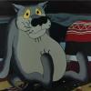
Ta Chris! Them moggies do seem to live in an interesting social matrix don't they? Hostility and amiability to each other and never consistently....😄 Characteristically decent of you Ian! With two lads on the cusp of preparing for possible further studies we have regrettably needed to prioritize their education over our righteous desire to see the planet before the asteriod hits/methane bloom/neocon dark age render this problematic... If you're still there in 5 years or so it may be a different proposition! Not kidding Simon! And I used to think my £50 Sennheisers were posh!..... :😬 It's always a bleedin' carry-on round here ain't it Keith? 😆 Grazie Giorgio: time - or rather primer - will tell.... Thanks Ced. It needs to be a 'feature' of the build given the mission involved I reckon. #radiobufton Help yourself Benedikt! Our house is just downslope from a ridge line facing west toward the Atlantic so you occasionally find the maritime airmasses do some quite creative things with the warmer end of the spectrum at day's end. We hadn't been living here long when my wife called me outside one evening at sunset to see vast parallel lanes of cloud shadow stretching all the way from the sunset in the West right across the zenith to the eastern horizon. I'd never seen such a phenomenon before or since. Not short of rainbows either with all the moisture coming in from the ocean... Good man! Ta Bill. 👍 Now to build some tiny dots and dashes for it to pick up! Sincerely hope that you're having/have had a wonderful time in-country Terry and that all went well for your son and his wife on their big day. 🎊 The greenhouse part of the build then. Been dreading having to tangle with all that clear stuff down the sides tbh as the glazing is such a distinctive visual feature of this lolvely aircraft that it warrants careful attention. Having reshaped and extended the various openings, as well as adding some brass framing as reinforcement, this has become slightly more complex undertaking than whacking a single slab in down either side as per the original kit part. First manouevere was to trace the openings from the kit onto paper in order to scan them in as a reference image to build a set of designs in the Silhouette software from: To establish some form of accuracy I generated a set of paper blanks with the cutter, eyeballed these one-by-one on the kit to make any adjustments, prior to starting to experiment with cutting various materials. Firstly this involved producing a series of plasticard blanks that could be offered up to the kit as the basis for more precise adjustments: I'd wanted to spend some time doing this with the cutter in order to establish its prospective usability for cutting shapes from plastic; here I used a combination of 0.35mm plasticard with the Portrait cutter on the 'coverstock heavy' setting (a heavier 2-pass value). This worked remarkably well as the above design could be easily quite snapped out of the surrounding plastic for use. These blanks were then refined further with files against the kit and rescanned in to the software for final drafting: ...eventually leading to these: I'm experimenting here with cutting the designs from both some screen protector material from a tablet and some standard PETG scrap packaging. Both cut very nicely and pop free from their surrounding without any undue force needed. In the shot below the small window on the left is screen protector, the larger section on the right PETG: Both score well on being optically clear enough for use (though the screen protector naturally has a slight edge in clarity due to its inherent thinness) The biggest concern is the lack of surface area for gluing such long runs of material into place - especially important to bear in mind as I remember how terribly fragile the bonding of the screen protector was when peeling off masking after paint on the Iron Chicken. I think on that basis, the PETG option just edges ahead here in terms of pragmatism whilst involving very little loss of quality in terms of the optics. It's also a toss up whether to use Gator's Grip or GS-Hypo so my gut tells me to try a little test mule first in this matter prior to committing to a single option. I mentioned previously how much I hate transparency work and don't want this to end up being the weak link.... More as it develops brothers and sisters. Tony8 points
-
Here we have Italeri’s old Leopard, in its 1A2 boxing, wearing Esercito Italiano markings. (I don’t know what unit.) At last! - the first of my 16 Leopard kits sees the light of day. This kit has been around a long time but it still bears up. It’s modular, allowing for a number of the basic build variations. I got mine from Italeri and Revell. Now that Revell has started to produce its own kits, it’s not clear what the future is for, say, the 1A5 version. The kit builds reasonably well and reasonably easily, although it has two problems with its engineering. First, for my money, there are too many butt-joints. Most of the tools and accessories on the upper hull attach to faint outlines rather than by pins, which makes them hard to position accurately. Worse, the side skirts have no positive location points, which is doubly tricky with the poor fit of the mudguards. I’ve reinforced the front-end joint with a plastic tab. Second, it’s plagued with mould slippage and seams. It seems the smaller the part, the worse those flaws are, and the harder they are to correct on the sprue. I’ve read that this version is nearer a 1A1 than a true 1A2, but the differences are minor, and I didn’t fancy over £20 on a replacement turret. I’m happy enough that the major changes from the original Leopard are in here: thermal jacket on the gun, exhaust grilles, new tracks (more on them later), and side skirts. The overall finish is Humbrol 86 light olive, which Giorgio N on this site and others on Armorama say does the trick. Under the watercolour, pastel and dry-brush weathering, I think it does too. If you’ve made it this far, here’s a few build tips you might find helpful. First, the turret. Fit of the top and bottom halves is poor and needs a lot of sanding and filler. Helpfully, though, you can leave some of the excess plastic to mark the join on the real thing. Fit of the mantlet is worse, leaving a large gap underneath. Mine is packed with plastic card. You may also find that, with the dust cover attached to the mantlet, the whole assembly meets the turret at a slight sideways angle. I’m not convinced the turret sits low enough on the hull, but from most angles you can’t tell. The rear basket is pleasantly easy to assemble, but some of the locating points are a bit sloppy and need filling. The smoke launchers are handed, and helpfully have ejector pin marks on the outer side - it would have been just as easy to put them on the inner side, wouldn’t it? And they’re the devil to remove. I’ve added wire cables to the gunfire simulator and the searchlight. For the latter, there’s a blanked hole in the right position that you can drill from inside the turret top. The radio antennae are very coarse; mine are fine florist’s wire. Now, those tracks. While I like the Italeri kit, its tracks are dreadful: stiff, chunky, and poorly detailed. The only replacements I’ve been able to find are very expensive Friul metal jobs, and really nice plastic ones from Meng, which now appear in their Leopard kits. I used those, and they turned out to be a nightmare. Five parts per link is pushing it a bit, but I can live with that. The real problem is that they’re supposed to fit together without glue, but they just won’t. The idea is sound: the end-connectors are integral with their bars, and carry the guide horns too, and you trap them between two inner faces and two outer faces. Much like the real thing, in fact. But the holes in the inner faces are too narrow for the pins on the outer faces, so you have to drill them out slightly with a 1mm bit. With two holes per part, and two parts per link, and 84 links per side, that works out at slightly more than four thousand turns of the drill. And still, the two sides may not meet perfectly, nor trap the connectors properly. Even when they do, moving links to any position other than dead straight can push the outer face away, and as soon as it goes, it will let go of the inner face too. It’s maddening. From bitter experience I can recommend: sod the instructions, and use glue. You can assemble quite a lot as straight lengths for top and bottom, leaving just the bits that bend round the sprocket and the idler, and the bits that connect them to the bottom run. Then you can attach those to the straight lengths, apply glue, and work them carefully into position before it sets - but even that will wrack your nerves. And you’ll still need four hands, possibly more, to do the final connections. Meng give you a jig and it works well. But it’s no help for those last bits, of course. And it’s made of the same plastic as the rest, so you daren’t glue your tracks together on it. I used Revell Contacta with the hypodermic applicator, applied to the sides of the assembled links. Good luck painting your tracks! I’ve not done that much retouching in ages. I could live with this easier if the result was better than other people’s tracks. But AFV Club uses only three parts per link for its Leopard 2 tracks, and they’re a genuine push-fit, with no less detail. If you use these tracks, be very careful with the connectors. The bars are hair-fine and can break just from being taken off the sprue or from being held firmly. There are spares in the box - but not as many as there are for the other parts. 84 links matches the kit tracks, and hangs a bit slack. 83 links would almost certainly be too short. Other points about the running gear: don’t worry too much about the sink marks. They’re largely hidden. The hubs are a bit of a loose fit with the wheels, but you can disguise it with careful painting and oil stains. And you can leave the return rollers loose, which can be handy for feeding the tracks in. The tyres have odd grooves across them. I’d read that they weren’t right, but then I saw pictures of a Belgian Leopard with them, so I’ve not sure what’s going on there. My view: filling 336 tiny grooves was more than I could bear. Properly assembled, the sprockets shift around a bit, which didn’t help with the tracks; but they turn as well, which did. On the hull, the undersides of the sponsons are moulded as part of the lower hull. That makes it a bit harder to fit the tracks, which is unwelcome, but it does mean you can close up the hull first and sort out any dodgy panel fit before the tracks get in the way. The one exception is the sprockets, for which you have to fit washers inside the hull, but they sit far enough forward that they won’t get in the way of work on the rear plate if you want to do it in this order. I think I will, with my other four Italeri / Revell Leopards. Closing the bow and glacis plates is hampered by a slight step that’s moulded into the lower hull sides right at the front. Next time I’ll sand that away before attaching any of the running gear. Fit of the rear plate is rough all round and needs a bit of help from filler and plastic card. The exhaust grilles help locate the rear plate, but they’re not a great fit either. The instructions would have you attach a few parts to the plate before fitting it; in future builds I’ll fit it, and sort out the grilles, first. After that, the upper hull is trouble-free, although the mudguards aren’t brilliant. The front ones (I used the full-depth ones that go with the skirts) sit a bit low. You can use very thin plastic to fill in the step where they meet the section that’s integral with the upper hull. The rear mudguards are OK, a bit thick on the lower rubber sections, but they’re so close to the towing hooks that it may not be possible to fit the tow cables. The tools have nicely detailed clamps, but nearly all are on the backs and will be hidden if you attach the tools the right way up. I’ll bet there’s a fiddly, expensive fix. I wanted to use the Meng grousers on the glacis plate, but they turned out to be too big, so I settled for the vinyl things instead. With so much hidden by the racks, it didn’t really matter.7 points
-
Hi, gentlemen, "Zvezda" has issued the most impressive model of the MiG-29 Fulcrum C in 1/72. It was powered by Aires resin (nozzles, cockpit) Eduard resin wheels, Part photoetched and Pavla canopy. And of course some details are from scretch. The main challenge is how to build in the Aires resin parts, which have been produced for the old Italery model. So, it is possible and for the Zvezda kit as well. With regards,7 points
-
Phantom FGR.2 XT911 228 OCU / 64 Sqn Coningsby, 1970 This is the 1/72 Fujimi kit with Modeldecal markings apart from the roundels, which are Xtradecal. I haven't built the Airfix Phantom yet, mainly because I have a fair stock of unbuilt Fujimis in the attic. I like this Fujimi kit - the panel lines are just about right and the shape and detail are good. I've gone back to the early days of the RAF Phantom with this one. I like the R/W/B roundels and glossy finish, and it now complements my Harrier GR.1 and Buccaneer S.2B in this scheme. Having looked at photos of the new Airfix kit, it seems to provide the tailplane with positive incidence - i.e. leading edge down. If you look at RAF Phantoms at rest the tailplane seems to come to rest the other way round - i.e. leading edge up - and this seems to make a big difference to the overall look. The Fujimi kit gives neutral incidence but I modified mine to give the at-rest look.7 points
-
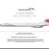
I present the Revell A350 in the cheerful “Expo 2019” livery carried by Air China’s B-1083 to promote the International Horticultural Exhibition in Beijing. I know that opinion is divided about the A350’s looks but beauty is in the eye of the beholder and personally I like its odd, quirky appearance. The superb Revell kit really does it justice. The kit was a straightforward and enjoyable build. Apart from a BraZ satcom fairing and a few small details the model is OOB. I was particularly taken with the engines and undercarriage which are both masterpieces of miniature plastic engineering. Although it looks complicated the undercarriage is actually easy to assemble, much easier than the Revell A330/340, but it’s essential to follow the instructions carefully and, in particular, put the brake discs on the right way round. (Don’t ask…) White paint is Halfords and the standard Airbus Grey on the engines is Holts HL Grey 01. Metallics are by Tamiya and Revell. I’ve never seen an authoritative match for Airbus Matterhorn White and after a bit of experimentation I used Mr Color 107 Character White for the wings, tailplanes and pylons. It looked OK indoors but when I took the model outside for the photographs it obviously isn’t grey enough so the search for the perfect Matterhorn White will have to continue. Livery decals are by TwoSix with Authentic Airliners windows. Ray has done a fantastic job with the decals which virtually fell into place on the model apart from a tiny bit of trimming round the number 2 doors. The only minor issue is that the winglet logos are a fraction too big (particularly noticeable on the inner faces) but nothing I can’t live with. Thanks for looking and thanks also to @Duncan B who supplied the kit. As always constructive criticism is welcome. Dave G One problem with the design of the kit is that you must install the nose wheel leg at an early stage, there is no way round it. Here's a tip to protect it using an expanded foam "bead" cut in half. The idea isn't mine - I pinched it from somebody on here, possibly Turbofan. Obviously it won't protect against dropping the model on the floor but it should save the leg from routine knocks.7 points
-
I'm not sure what my fastest build was Giorgio but this must be close. Not a skinful Stuart, sadly - a very cultural 'Night at the Oscars' by the local amateur dramatic lot. Fun! Thanks Bill (Some blank lines removed!!) Thanks Simon Can I have cheese on mine please? And some bacon? Oh yes, and chips - I don't like those skinny things. Thanks Bill - it may not be a great kit, but it is quick! Thanks Andy - I hope you find it! Bits stuck on the bottom: on Flickr Missiles separated from the gates: Those ejector marks - yuk. They are on the 'inside' but hey, even I have standards. Just not very high ones. They've been scraped and sanded a bit and stuck on sticks ready for painting. Time to insert the pilot. Oh dear: He's got his legs crossed (??!!) and would only fit sitting to the side of the stick. Unbelievable! Luckily the chubbies fit: … so I'll need to paint one up. Cleaned off with IPA after filling the (small) joins, I just need to paint the pilot and mask the canopy then she's ready for primer:7 points
-
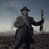
This diorama is complete~! In 1947, during the civil war in China, a professor was fleeing the city and passing a Japanese tank type 95 that was destroyed in the Second World War. END6 points
-
Evening All, If you do not know what the Caproni Ca 5 looked like here are a couple of links: https://www.alamy.com/italian-caproni-ca5-bomber-plane-ww1-image66158621.html https://1000aircraftphotos.com/Contributions/SmithGaryL/8921.htm It was a trimotor bomber designed in 1917 to replace the successful Caproni Ca 3 which was used by the Italians to bomb targets in Austria. This required the aircraft to fly long distances including over the Alps, so a third engine was considerd to be desirable in case one of them malfunctioned on the long flights. Unfortunately the engines chosen to power the Ca 5 were not particularly reliable, so although the airframe was sound, the aircraft was rather less so and the Ca 3 soldiered on beside its successor to the end of the war. However the type remained in service until the early 1920's and was used by the Americans. I am building this as part of a group build in memory of Des Dellatore on another site: Des was a superb scratch builder who made 1/32 scale models of very early aircraft which are now rightly displayed in a museum. I cannot find any kit of this machine which makes it an ideal subject for a scratch build to his memory, although my model will be 1/72 scale. Interesting features of the type include the engines, triple tail unit, twin booms a platform for the rear gunner above the engine, and double wheeled undercarriage: markings seem to have been relatively straightforward too so can be easily made at home. There is some reference material on this type - certainly enough to be able to make a reasonably accurate model, although as usual with WW1 types, colours are interpreted in different ways in the sources. I have assembled my kit: styrene sheet of various thicknesses, strip, rod, wood, and other materials as needed as the build progresses. I have started by marking up the fuselage nacelle on a block of wood and am ready to start carving: and I have cut some styrene sheet for the wings. These are quite thick so to get the thickness and aerofoil section I am trying out an idea. I have cut a piece of 30 thou card which has been bent in hot water and laminated this with a strip of 20 thou card which was laid over the top. The 30 thou strip was wide enough to extend to the rear spar, and then a strip of 20 thou card and 10 thou card was laid along the trailing edge of the 30 thou card. Here are the strips before they were glued together: The underside will be sanded and filled to give the aerofoil section and any joints smoothed over with filler: hopefully if there are any remaining marks these will not be visible because they will be under the wings. Finally I have cut some wood ready to be carved into propellors: Thanks for looking. P6 points
-
This is my conversion of a Monogram 1/48 Douglas DC-3. It was a rather complicated excersise, but it can be done.6 points
-
Almost every model I have seen so far made form this kit presents a problem regarding the insertion of the lower wing in the fuselage. It is usually solved with a flat butt joint not shaping the corrugations on a curve, but that's not how things are in reality. The issue is that the kit's fuselage cross section is (surprise!) not very accurate, and it's more boxy (squarish) than it should be. The drawing bellow shows the differences with some exaggeration -but not much-, to make the point: You can see that the lower half of the wing extends further, while it should be the upper half the one that should do it, since it "mounts" over the fuselage in real life: This is how things should be (as per the real thing), and the pencil line shows what photos of the real plane show : Not only that, but the wing should be inserted with a noticeable angle of incidence: This means that some complex shaping will have to take place on both lower wings to accomplish a realistic joint, plus meet the spar, plus achieve to be symmetric to the other wing, in all axis. Trembling and biting nails yet?6 points
-
The additions are checked as always with yet another dry fit:6 points
-
With regard to the tragic Ethiopian Airlines crash, there appears to be more it than what I'm reading in the papers. Here is the latest from Aviation Week: https://aviationweek.com/commercial-aviation/ethiopian-crash-data-analysis-points-vane-detachment?NL=AW-05&Issue=AW-05_20190411_AW-05_553&sfvc4enews=42&cl=article_1&utm_rid=CPEN1000000985591&utm_campaign=19193&utm_medium=email&elq2=62aae782c6e845adbb1e9b2d483cbe76 "As the investigation continues into the causes of the Mar. 10 Ethiopian Airlines Boeing 737 MAX accident, sources close to the probe say flight data recorder (FDR) data firmly supports the supposition that the aircraft’s left angle-of-attack (AOA) sensor vane detached seconds after take-off and that, contrary to statements from the airline, suggests the crew did not follow all the steps for the correct procedure for a runaway stabilizer. "Detailed analysis of the FDR trace data shows that approximately six seconds after liftoff was signaled by the weight-on-wheels switch data, the data indicate the divergence in angle-of-attack (AOA) and the onset of the captain’s stick-shaker, or stall warning. Almost simultaneously, data shows the AOA sensor vane pivoted to an extreme nose-high position. "This, says one source, is a clear indication that the AOA’s external vane was sheared off—most likely by a bird impact. The vane is counter-balanced by a weight located inside the AOA sensor mounting unit, and without aerodynamic forces acting on the vane, the counterweight drops down. The AOA sensor, however, interpreted the position of the alpha vane balance as being at an extreme nose-high angle-of-attack. "With the stick shaker active, the trace indicates the crew pushed forward on the column to counteract what they believed were indications of potential approach to stall. The aircraft, now in level flight, also accelerated rapidly as its power setting remained at 94% N1 thrust used for take-off. This was followed by some manual trim inputs using the thumb switches on the control column. "Seconds after speed advisories were heard, the crew raised the flaps. With the autopilot turned off, flaps up and erroneous AOA data being fed to the flight control computer (FCC), the stage was set for the MAX’s maneuvering characteristics augmentation system (MCAS) to activate. This is indicated by approximately 8-sec of nose-down stabilizer movement, which was followed by the use of manual trim on the control column. However, with the MCAS having moved the stabilizer trim by 2.5 units, the amount of manual nose-up trim applied to counteract the movement was around 0.5 units, or roughly only 20% of the amount required to correctly re-trim the aircraft. "Because of the way the aircraft’s flight control computer P11.1 software worked, the use of manual trim also reset the MCAS timer, and 5 sec. later, its logic having not sensed any correction to an appropriate AOA, the MCAS activated again. The second input was enough to put in the full nose-down trim amount. The crew again manually counteracted with nose-up trim, this time offsetting the full amount of mis-trim applied by the latest MCAS activation. "By then, some 80% of the initial MCAS-applied nose down trim was still in place, leaving the aircraft incorrectly trimmed. The crew then activated the stabilizer trim cutoff switches, a fact the flight data recorder indicates by showing that, despite the MCAS issuing a further command, there was no corresponding stabilizer motion. The aircraft was flying at about 2,000 ft. above ground level, and climbing. "The crew apparently attempted to manually trim the aircraft, using the center-console mounted control trim wheels, but could not. The cut-out switches were then turned back on, and manual trim briefly applied twice in quick succession. This reset the MCAS and resulted in the triggering of a third nose-down trim activation lasting around 6 sec. "The source says the residual forces from the mis-trim would be locked into the control system when the stabilizer cut-off switches were thrown. This would have resulted in column forces of up to around 50 lb. when the system was switched back on. "Although this could have been reduced by manually trimming the aircraft, this did not occur, and the third MCAS activation placed the aircraft in a steep nose-down attitude. This occurred with the aircraft near its peak altitude on the flight—about 6,000 ft. The engines remained at full take-off power throughout the flight, imposing high aerodynamic loads on the elevators as the crew attempted to pull back on the columns. "Vertical acceleration data also indicates momentary negative g during which the AOA sensor on the left side unwinds. This is seen as further validation of the theory that the external part of the alpha vane was detached as the apparent change in angle indication could only be explained by the effect of negative g on the counterbalance weight, forcing it to float up inside the sensor housing. In addition, the captain’s stick shaker also comes off twice in this final phase, further reinforcing the severed vane notion. "The source indicates the crew appeared to be overwhelmed and, in a high workload environment, may not have followed the recommended procedures for re-trimming. Boeing’s stabilizer runaway checklist’s second step directs pilots to “control aircraft pitch attitude manually with control column and main electric trim as needed,” according to one U.S. airline’s manual reviewed by Aviation Week. If the runaway condition persists, the cut-out switches should be toggled, the checklist says." Cheers, Bill6 points
-
Properly finished! RFI thread here: Thanks for all the input and support!6 points
-
Evening All, Moa has recently posted his Airfix Hannover HaWa F3 cabin conversion, which has lozenge camouflage on the wings. I noted that I had hand painted the lozenge on this Airfix Albatros which I put together more decades ago than I care to remember...... The model represents the D V of Lt von Hippel of Jasta 5 who was killed when he entered a steep dive and his wings fell off: a weakness of this aircraft which was caused by the sesquiplane wing structure. Under the high stress of a steep dive the lower wing spar twisted and failed with catastrophic consequences. The designers tried to rectify the problem by adding a small stiffner strut from the leading edge of the wing to the base of the V strut, but most pilots refused to go into a steep dive in persuit of an opponent. Lt von Hippel was an early victim of this problem. I have also painted the distinctive fuselage marking in red: some sources give it as black. There are also differences of opinion as to the shape of the arrow but as I had not seen any photos of the machine when i made this model, I used the only published source available to me. The lozenge markings were painted by hand, but I did not attempt the rib tapes as I did not have a suitable pen. I am also aware of the shortcomings of the Airfix kit, (one of thier earliest relaeses, from I think, 1958). In any event here is the model - about 45 years after I painted it..... Thanks for looking. P6 points
-
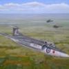
Hi all. The Fairey Rotordyne was yet another great British idea that came to nought, in my mind it had so much potential but this was never realised, however, what the programme created was a very unique looking aircraft that performed very well during it's development and which has it's place in history. I started this little project as a gap filler for another build but this kit in fact took more of my time and effort simply because I did not realise the task I had set myself. The model is finished as one of the earlier forms of the prototype so the distinctive middle vertical tail surface was not required but the strengthening struts for the undercarriage had to be fabricated, these were later removed as development progressed. Also, the remaining vertical tail units were cut and angled out as it would be when the aircraft was on the ground. As with most prototypes an instrumentation boom was also fitted so this was mad from Albion Alloys and scrap PE. That was the easy part, the fit of many of the parts was not the best and probably to be expected from a kit of this vintage and much time was spent coaxing the parts together and filling but the worst area by a country mile was the cockpit glazing, this was truly horrendous and after much work I just could not go any further and called it a day, it was improved but not brilliant. The next and by far the largest and worst job was removing all the 20mm cannon holes that were trying to pass as rivets, this took several passes of filler as when I sanded down some filler just disappeared due to the shallow nature of the cannon holes. As hard as I might I could not see these rivets prominent on the real airframe and being NMF I had to remove them, I think I got most of the blighter's! Another little job ( he said) was to modify the propeller hub. The kit would have the propellers running against the front of the engine nacelle so after looking at pictures I noticed there was a gap between propeller and nacelle so I made an extension to the hub behind the propeller for both sides to create the required gap. The model was sprayed in Alclad II paints, paying particular attention to the rotor blades as these are so important to the look of the Rototdyne. One last job was the decals, the kit items were way to big and left no room between the bottom of the windows and the bottom edge of the fusalge so I made my own, along with the Fairey logo and ' Rototdyne' decals on the rotor pylon, these two unfortunately rebelling against the decal solution. So on reflection, did I enjoy the build..no. Am I happy with what I achieved....yes. Would I make another....I would rather not. Hope you like it, pics are not great but will try to get better ones soon. Thanks for looking. PS. Just realised before posting that I had not attached the instrumentation probe so you will find it on the last picture, god bless her, fighting till the last....6 points
-
I thought I'd strike while the iron was hot and give it a lick of paint, patience is not one of my strong points, paint is the 50x50 mix I mentioned in an earlier post of xf49 khaki and xf 66 light grey, how it stands at the minute, the pre highlighting didn't really work out, the paint was thin enough, but maybe not enough contrast as I used buff not white, Here you can see my daughters tank wheel painting tool, which has been successfully masking all my tank wheels of the last three or four builds, a gods send for 99p I must clean it up and pop it back into her pencil case, after the tiger gb of course, cheers all, hope you like the colour, I'll weather the bejesus out of it next🤓6 points
-
I finally decided which registration the model will bear (a secret for the moment). Consequently, since that registration had the aft cargo haul, and the kit presents none, the door is drawn with pencil and the part excised, carefully. The actual door did not look like the removed part (it was smooth and had structure behind), so a new one will have to be made to replace it: In a sequence that very much reminds me of Jorge Luis Borges' "Garden of the forking paths", where every path divides in two, now I have to create that aft cargo haul itself, adding floor and a corrugated bulkhead:6 points
-
Assembly of the tail continues, and the tail wheel complex is under way. The kit's tail wheel is inaccurate both in shape and size, so it's replaced, as were the main wheels. Furthermore, the injected parts in the kit associated with the tail wheel are laughable miseries, and were mercilessly thrown in the trash can:6 points
-
Not entirely sure where to post this, but I figure it was intended to be used as an Armored Personnel Carrier of sorts.... 1/35 scale, Trojan Rabbit from Monty Python and the Holy Grail. Built for a club theme: “Movie subjects”. (Still looking for a suitable “Arthur, King of the Britons” figure in 1/35...) Scratchbuilt model was scaled up from a 1/72 paper model. Inner frame of styrene and balsa. Logs are carefully selected sticks collected around the neighborhood. -Bill5 points
-
Hi dear folks This is my very first effort of bulding a model of F-5 from AFV CLUB.As many of you know the kit is superb and detail is brilliant. I used Martin-Baker IRQ-7A ejection seat that comes with AFV CLUB Saeqeh kit.(Iranian version of F-5E) Colors are mixture of CSI Creos Mr. HOBBY , Mr. COLOR and AKAN paints. Sorry for bad quality photos, I haven’t provided myself a photo booth yet!5 points
-
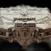
Some of you may have seen my earlier WIP posts about creating this "Type S Scout/Courier" from the Traveller Sci-Fi RPG universe from concept art, through 3D modeling, 3D printing, prep and painting. My previous WIPs have all been at 1/350 scale, but I was intrigued by a suggestion to build it at 1/285 scale since it's a popular scale for Micro Armor war games, Warhammer 40K Epic scale and a variety of other terrain and miniatures. In the process of creating a larger scale build, I completely overhauled the geometry of the model, adding quite a bit more hull paneling detail that resolved very nicely in this slightly larger scale. I also added a number of weapon turret variants and built out the sensor pods found in the original artwork. All hull markings were airbrushed on with the help of custom vinyl paint masks that I created except for the small "Poni" symbol on the starboard side and the hazard markers on the rear airlock, which are custom water slide decals. The engines are not rocket exhausts, but "thruster plates", which are part of the ship's Manuever Drive unit, a sci-fi reactionless thurster. Thruster plates emit a bluish glow, like Cerenkov radiation, when operating. Hope you enjoy my latest model!5 points
-
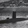
I’ve recently completed my 1/72 scale 80’ Elco PT boat, United States Navy hull number 620. A short history of PT 620: PT 620 was one of the last group of 22 Elco 80' PT boats to be laid down & launched in 1945. She had a full complement of weaponry - four 21 inch torpedoes, a 37mm canon, a 20mm Oerlikon, a 40mm Bofors, four .50 cal machine guns, & two rocket launchers. She did not see action as WWII hostilities had ended. 620 was one of four boats that remained in service after WWII, under the USN's Operational Development Force, and were the last WWII PT's in service in the US Navy. She was transferred to South Korea in 1952 and re-named Jebi (PT 27). She was returned to USN in 1963 and was scrapped in 1964. The build was started in November, 2017 & completed in April, 2019. Using a hull from a Revell green plastic PT 109 kit #310, I scratch built the model from the deck up using plastic card, rod and stretched sprue, balsa wood & bits & pieces found around the house. I painted the model in the Elco grey paint scheme used after WWII and during 620's service with the South Korean Navy. Torpedo colours include a primer grey nose cone and transparent yellow over steel paint colour body to simulate the actual steel torpedo bodies rubbed down with 'Crotin Oil' as a corrosion inhibitor. The Work in Progress thread can be found here. The following purchased parts were added to the build; - Four Attack Squadron Mk XIII Torpedos - Four .50 caliber machine guns, one 37mm canon, and one 40mm Bofors gun from Atlantic Models. - Four Shapeways 3D printed torpedo roll off racks - One Eduard PE ammo belt set - Syren Ship Model Company 63mm dia. rope in tan colour. - Shapeways 3D printed -1/72 USN PT Crew Set 204 - Tamiya display case Here are a series of walk around photos showing the completed model. It was a fun build & I learned a lot about the Elco PT boats. Thanks to many of the Britmodeller members who stopped by the build thread & provided comments & advice to keep me focused on completing the build as accurately as possible, in 1/72 scale. Thanks for looking in. John5 points
-
Corrected & improved HobbyBoss kit with Aires cockpit, Eduard Bullpups and EagleStrike decals. Hope you like it Best regards from Czech. Andrew5 points
-
Thanks for your comments 🙂 Engine Section, Hangarbays and Trenches are airbrushed. I then cutted the FO's in the trenches using a sharp micro chisel. Now it's about preparing the lighting. cheers, Dirk5 points
-
Morning all, Time to rescue this thread before it falls any further down the page. I've been busy clearing up a couple of other builds and now these are done I can get back to this. I'm away for a few days so brought the Patton with me to get a bit done on it. First task was to remove the late pattern air cleaners as the resin set provides new ones. This was harder than I expected and resulted in me cutting away a rectangle of fender which I'll replace with plastic card when I'm back home. This way the new parts will sit correctly. I then had a play with the lower hull which had been assembled badly, the main issues issue being the idler mounts being on upside down which prevented the hull fitting together. This was corrected, and the upper hull sides removed and refitted correctly. The gap has now been filled ready for sanding later. The road wheels arms have also been fitted. I've also removed the rails from the turret sides and will replace with wire later. More soon All the best Ben5 points
-
This thread, and the first posting in "Burn down their hanging trees" are essential reminders of what WWII was about: beating into submission one of the most evil regimes ever. A big thank you to every allied soldier who gave his/her time, health and life for the effort! Richard5 points
-
1/48 Dragon Ju 188E, Verlinden Compass/gun Alignment Platform with accessories, Monogram Bomb loader & fuel cart, Eduard Brassin SC 500 Kg bombs, Still have a couple CMK figures to paint & add, John5 points
-
I've never used Gator Grip although it's been on my to-buy list for eons now. I will say that I would feel comfy using GS-Hypo for that particular task. The GS-Hypo is nice in that once it's cured, you can trim it very easily with a nice sharp blade. Another option to consider is to use GS-Hypo (or Gator Grip) at strategic points, then use some diluted Formula 560 or other PVA glue... for example use GS-Hypo on corners and areas where you have the most surface area, then apply diluted PVA with a cocktail stick to the remaining seams/gaps - it will wick in there nicely. Several applications of the diluted PVA on both outside (and inside faces if possible) should provide a nice strong bond. Even when diluted it dries pretty quickly. You could also add a touch of black paint to the PVA if you wanted replicate rubber seals btw... I'm back now. I think Perhaps I'll even get some modeling done soon5 points
-
Well it was back to work and the lunchtime tug project and it was time to tackle those bulwarks. Back in post #121, paper templates were made to then be transferred onto plasticard but unfortunately, for one reason and another they didn't work very well. I think that it was down to the lack of strength in the support-deck join, so plan 'B'. Although not very clear, I decided to produce the bulwarks with thinner plastic of about 25mm lengths, laid end-to-end like bricks. Plasticard re-enforcement was added between the supports with the same thinner plasticard After a few lunchtimes... Nearly there but I'm not looking forward to the back-end, that'll be a 'pita'. It's not perfect by any means but better than my plan 'A' and some cosmetic work will need to be done. Stuart5 points


This leaderboard is set to London/GMT+01:00