
Leaderboard


Popular Content
Showing content with the highest reputation on 13/07/13 in all areas
-
Inspired by Artur's miniature I decided to build my own Su-22. I used Eduard's kit (in fact KP with some etched parts and resin cockpit interior). OOB, without any modifications,except decals for polish aircraft ..and a few pics from the building:4 points
-
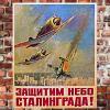
Russian Udaloy Class Destroyer The Vice-Admiral Kulakov, pics thanks to Panzer Vor.4 points
-
Desert Snake Hi mates, here are some pictures of my last year finished Airacobra from Eduard. I`ve used the old but great Profipack with photoetched parts, Express Masks and no less than 6 different variants of paint shemes. Additional I used both CMK accessories for engine compartment and front armarment. The model you see represents an aircraft of 346. FS, 12.AF, Noth Africa.The 346. was the last USAF unit using the P-39 in Europe. Only used as an attack aircraft, as this type didn`t rocks as dogfighter against german fighter ! The built was pure fun and gone straight forward! Only minor mods are necessary to convert this model to a L-1-BE type. A wonderful source with all necessary informations is Book No. 6129 of MMP`s Yellow Serie. [/url]4 points
-
Oookay, finally calling it done. (Though now I look at my photos, it truly does needs the nav lights at the wingtips.....one final doddle. But no more pics - it's safely in the cat-proof Detolf now!) Lee, thanks a million for the great idea!!3 points
-
Operation Harmattan Libya 2011 Revell 1/48th kit [/url]2 points
-
Hello Folks, I`ve always wanted to build a model of the earliest Wessex `Junglie' version which were specially stripped out HAS.1 anti sub versions that were painted overall Light Stone and rushed out to Borneo to replace the Whirlwind Mk.7 `Junglie`s' which were operating from primitive jungle heli pads. My original intention was to use the Revell Wessex HAS.3 kit but when Italeri announced that they were doing the same version I held out for one of these instead and here is the result, backdated to HAS.1 status and depicting XP142/J `Mr. Jinks' of 845 NAS, which was later converted to HAS.3 status and went on to become the famous `Humprey' of Falklands fame and now resides in the Fleet Air Arm Museum! Here is the build thread; http://www.britmodeller.com/forums/index.php?/topic/234942543-48th-scale-wessex-has1-junglie/ The `Mr Jink`s' artwork inside the red circle on the nose is hand painted, as is the 845 NAS insignia although a very kind Britmodeller (Dave!) has done me some decal replacements which are on their way from the USA,...what a kind bloke! Two of the emergency escape windows have been opened up to let a bit of cool air in and a `Gimpy' GPMG from the Airfix Lynx kit has been mounted in one of them. Anyway enough blurb,...here is the model; And here is it again with my next Junglie lurking behind, the Italeri Wessex HU.5! Hope you like it, All the best Tony O2 points
-
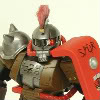
Just finished the build this week. I used the canopy and gear legs from the Heritage Aviation kit, Quickboost wheels and exauhsts, Aeroscale decals for the markings and custom decals for the prop:2 points
-
Built from the box with the exception of a Wolfpack MB Mk4 ejection seat. I think this is Kinetic's best so far although the instructions are still lacking in places. I can't wait for a C.1 especially as Furball Aero have a sheet for USN/USMC F-21's coming out. Stephen2 points
-
OK , this is a prime example of what I did a rant about earlier in the year. Why some people feel it is so necessary to boost their own ego's by pointing out a inadequacy on someones build that isn't even the fault of the builder is beyond me. Why would it be necessary to anybody's benefit to say the tail wheel is 5 degrees off ? Only the most anal of builders would even know or even come close to caring. All this type of so called accuracy information does is detract from an otherwise AWESOME build. It behooves no one to point out these flaws in open forum on someone else's build. If you want to point out inaccuries then build it yourself and review your own build to point out the flaws. Great build Dave! It certainly doesn't need to be detracted from by anal-ytical B.S.2 points
-
[/url]2 points
-
Hi all, Esci 1/48 Saab Viggen. Back end of the 80's I paid £1.98 at Poundstretcher for the kit and its been stashed for almost 26 years so decided to build it. A tin of paint today cost me £1.60 and the ejector seat £6. Brian.2 points
-
I rattled this together in between the paint passes on my Fokker D.XXI. I painted it in the variant that the old tool Zero was supplied in as I had those decals spare from an old Techmod sheet. However, these decals were so fragile that they started breaking apart just if I looked at them the wrong way, so I had to resort to painting the Hinomarus (no big deal - a red circle) as well as the blue stripes. The fuselage sash was the tricky one and it ain't perfect by a long shot, but it'll do. It'll have to! My only gripe with this kit is the canopy framing. Not only is the framing too thick, but it has large radius curves in the corners making it impossible to mask properly unless you have a pre-cut mask, like Eduard's - which I did. Other than that, a great little fun kit!2 points
-
My best wishes to all the staff, hope they all find employment soon, it must have been a difficult few weeks for them all.2 points
-
After my Spitfire build I though of continuing my WW2, 1/48 theme. I am hoping for a less stressful build and less mistakes. For that I will try to be less adventurous and more patient. The starting point is Tamiya's kit, Aires Cockpit, Master gun tips and since I took the photo below added the Eduard FE205 (to compensate for an accident I had with the photo-etched of the Aires set) and an excellent decal sheet from Lifelike Decals (48-018). After the Spit I am a bit scared of the Tamiya decals and I want to experiment a bit, once I get my hands on some suitable solvents. Being an airbrush novice I am going for the standard RLM71/02/65 which is easy to handle and building the aircraft of Maj. Ernst Freiherr von Berg (Kdr. III/JG26) Started with the cockpit but I could not resist myself and added a few bits and bobs... a And airbrushed with a custom mix of RLM02 that seemed ok... One thing I wanted to do was add a bit of character in the cockpit. Going past the confusion with the colours (gray floors, tan floors) which at the moment I have limited resources to clarify I decided to add some padding on the seat, much like the one from Cutting Edge in their 1/32 replacement. I just loved it when I saw it. I made the padding from some led foil. Some paint chipping on the top will be sorted later... I have added the harness and instrument panel from Eduard as the one from Aires got damaged (don't ask...) Cockpit painted, weathered, dry-brushed and approved by my wife... Comments and suggestions welcomed as always...1 point
-
Just a couple of pictures of an SAR HU MK5 to go with the HC MK4 I recently completed.1 point
-
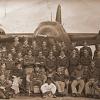
The Vickers 'Bullet' is one of those Great War machines which has been largely forgotten, some might say deservedly so, as its actual service record was far from distinguished. It has, however, points of interest about it, beyond the attraction of its obscurity for those who like the 'odd ducks' of early aviation. When it first took to the air, in its earliest iteration, its performance was extraordinary, and the type provides an excellent illustration of the difference between a good flying machine and a good fighting machine. It was employed in areas which were, at the time, viewed as backwaters of little importance, but which would prove of great significance in final stages of the war, and take on even greater importance once the war ended. The genesis of the type was a design of the chief test pilot for Vickers, Mr. Barnwell, and 'Barnwell's Bullet' was built without the company's approval in the autumn of 1914. Mr. Barnwell was a better pilot than he was a designer, and his machine broke on its first usage. Mr. Pearson, a designer for Vickers, saw some promise in the design, however, and re-worked it into the E. S. 1 (Experimental Scout 1), which flew first in August, 1915. It had a top speed of 114 mph, and extraordinary aerobatic ability. When this machine was sent to France for service trials at the end of 1915, however, pilots reported they had a very restricted view from the cockpit, owing to the width and round section of the fuselage, and the placement of the unstaggered wings. Six were ordered for further experiment, and eventually fitted with Clerget motors and a Vickers gun synchronized with the Vickers-Challenger gear; further service trials in May of 1916 received bad marks from pilots who much preferred the Dh 2 pusher scout in combat. In the summer of 1916, Vickers attempted to put things right with the design, reducing the width of the fuselage by leaving it flat-sided for most of its length. Now denominated F. B. 19, this was offered to the R.F.C. and foreign air services. Czarist Russia ordered fifty of this model, with deliveries beginning at the end of the year. Several were taken on by the R.F.C., and fetched up on Home Defense duty. Vickers further revised the design, giving the wings pronounced stagger. This F.B. 19 Mk II version did attract some interest from the R.F.C., as it appeared just as the German Albatros fighters were coming into service, and whatever its faults in pilot vision, the 'Bullet' was faster than the Albatros. The first example of the latest version, inexplicably, used the same wings as those of the un-staggered version, with the result that its wing ribs cracked in service trials during November. A dozen had already been ordered, but the need of redesigning the wings' structure delayed their delivery into spring of 1917, and that was the limit of the delivery of the F.B. 19 Mk II to the R.F.C.. It was decided to send these on to the Middle East, where English forces had suffered reverses at Gaza, and expansion of the fighting in Balkans loomed with the impending entry of Romania into the war. The 'Bullets' arrived in June of 1917, with several being sent on to Macedonia, assigned to No. 47 Squadron, and the rest being retained in Egypt, taken on strength.by No. 14 Squadron. They were used as escorts and interceptors, serving alongside such types as the Dh 2, the Martinsyde Elephant, the Bristol Monoplane, and the B.E. 2c and B.E. 12, opposing Albatros single-seaters and Rumpler and A.E.G. two-seaters. In Egypt, the 'Bullets' were passed on from No. 14 Squadron to a newly formed unit, No. 111 Squadron, in August, 1917. The problem of poor visibilty remained, and short range added a further handicap in these theaters, and only a handful of victory claims (and these only of the 'down out of control' variety) were ever posted up by pilots of the "Bullet' in the R.F.C. When more modern types reached the Middle East command, the 'Bullets', along with the rest of the former grab-bag equipment, was retired from combat, with several lingering on as trainers till the end of the war, and possibly even shortly after. This machine, A5231, is one of those retained in Egypt. It was assigned first to No. 14, and passed on to No. 111. It flew from Dier el Balah, not far south of Gaza City, and the lines the Turks had held against Gen. Murray in the spring of 1917, but which were broken by Gen. Allenby that autumn. The model is a scratch-build, and it is hardly surprising that is necessary to get a model of this type. My interest in it was sparked long ago, when I learned of its existence in my old Harleyford 'Fighters, 1914-1918' volume. A series of pictures of No.111 Squadron's equipment in an issue of Cross and Cockade bought a good while back included an identifiable picture of A5231, which got me thinking a model could be built, and when the Windsock people put out a monograph dedicated to the type, it seemed the time was right to start cutting plastic. It was an interesting project, and the first small scratch-build I have done in a while. An account of the build can be found here: http://www.greatwaraviation.com/forum/index.php/topic,5210.0.html1 point
-
After a long time, here is the finished Heron. I only added the antenna wire since the last post. I hope you enjoy. Cheers, Marcos.1 point
-
Hasegawa kit with Zoom photo-etched parts from Eduard, decals from Eagle Strike Range; except of them, i built my Sabre straight OOB and i had lot of fun. Paint with Gunze's acrylic H330, H331 and H56 for the blu (i know it's not the right PRU blu, but for me looks right!). Hope you like it And now... a couple of Sabres! thanks for looking ciao Ale1 point
-
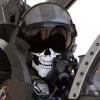
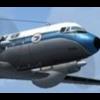
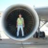
It's a little bit late, but here are some pictures from the Phantom Pharewell event at Wittmund air base, Germany on June 29. Luckily, the rainy, cold and miserable weather started to clear just that day. Cheers Jeffrey1 point
-
Good afternoon colleagues. I want to show work строилось все здесь http://scalemodels.ru/modules/forum/viewtopic_t_46055.html1 point
-
Hi everybody, I've just finished H.B.'s F9F2-P Panther, 1/72 nd scale. A very pleasant kit to put together, almost no sanding paper nor putty were used . H.B. proposes 2 gloss sea blue painted Panthers from VC-61, the unit that operated thes planes during the Korean conflict, in 1951 I chose to represent my model with folded wings and lowered stabilators : I added weight in the nose, the seat belts to the seat and the FODs : My gloss sea blue was toned down by using semi-gloss acrylic varnish . The decals were "sensitive" and concentration was needed to put them to the right places without deteriorating them . Personnaly, I think the windshield and the canopy sit too high compared to the pictures of the real planes, but tht's all right, I had a lot of pleasure to put it together an I hope more NAVY planes from that period of time will be released by H.B. Critics and comments always welcome, Cheers, Pierre1 point
-
This was roughly the equivalent of the F86D Sabre as both were radar equipped single seaters flown in 1949. Although about the same size physically it was much lighter and had less power, having the Russian equivalent of the Nene. Performance was quite good but it was let down by handling problems at high speed, landing problems in a crosswind and by the radar. Two prototypes were flown, this represents the second, but no production orders were placed. The kit went together quite well, not quite as easily as the other Prop & Jet kits, with some fiddly bits associated with the landing gear. One retraction strut for the main u/c could only be fitted (by me!) by tacking it to a toothpick and inserting it into the depths of the wheel well. Once glued the toothpick had to be broken off and the rough bits attacked with various implements. The outrigger wheels look very fragile and easy to break off. The kit is no longer available from Prop & Jet but Linden Hill still lists it (as of Sept 2013). A-model have produced a plastic version. It would be interesting to compare the two John1 point
-
US Mk 23 MTVR Cargo Truck Trumpeter 1:35 History The Medium Tactical Vehicle Replacement (MTVR) is a family of all-terrain cargo trucks manufactured by Oshkosh for the US Navy and US Marine Corps. The MTVR was initially ordered to replace the existing medium truck fleet under the US Marine Corps programme. The vehicles were extensively deployed in Iraq and Afghanistan. The Oshkosh vehicle can transport troops, fuel, water, food and supplies. The vehicle will also be used to tow the M777 lightweight 155mm howitzer. More than 11,000 MTVRs have been delivered to the Marines and the Navy Seabees to date. The MTVR is available in nine variants including MK23, (the subject of this kit) and MK25 Standard Cargo Truck, MK27 and MK28 Extended Cargo Truck, MK29 and MK30 Dump Truck, MK31 Tractor, MK36 Wrecker, MK37 HIMARS Resupply Vehicle, 4x4 Short Bed Cargo, 9-Ton Load Handling System 6x6, and 16.5-Ton Load Handling System 8x8. The vehicles feature a welded all-aluminium cab mounted on a torsionally rigid channel section chassis frame. The conventional layout houses the engine at the front, crew cab in the middle and troop/cargo section in the rear. The crew cab accommodates three marines. The standard MTVR cargo variant has a length of 8.02m, width of 2.4m and a height of 3.5m. The curb weight of the basic cargo variant (MK23) is 12.6t. The trucks can be integrated with Oshkosh TerraMax UGV technology for conducting unmanned operations. The crew cab and cargo compartment are equipped with an MTVR Armour System (MAS) to protect the crew from 7.62mm M80 ball rounds and 7.62mm Armour Piercing (AP) rounds. The mine protection kit can protect the occupants from mines and improvised explosive devices (IEDs). The bottom of the vehicle is provided with aluminium armour and rolled homogeneous armour (RHA) to withstand the impact of grenades and mortar rounds used as mines. Powered by a Caterpillar C-13 six-cylinder diesel engine coupled to an Allison seven-speed automatic transmission and torque converter, and an Oshkosh single-speed transfer box. It provides a power output of 440hp. Each variant is equipped with Oshkosh TAK-4 independent coil-spring suspension, which provides superior mobility and allows each wheel to move independently on the uneven surfaces. The vehicle features anti-lock brakes with automatic traction control. The Central Tire Inflation System (CTIS) allows the driver to select tire inflation pressures according to vehicle payload and terrain type. The vehicle has a maximum speed of 105km/h and on-road cruising range of 483km. It can traverse a 60% gradient and 30% side slope with its maximum cross-country load and can ford waters up to 1.5m deep. It can be internally transported by C-5, C-17 and C-130 Hercules transport aircraft. The MK23 cargo variant is airlifted under-slung by CH-53 helicopter. The Model The kit comes in the now standard, and in my view, very attractive, and sturdy box with an artists representation of the MTRV Mk23 on the front towing an M-177 155mm howitzer. On opening the box is full to the brim with nine sprues of light grey styrene, three separate parts for the cab and bonnet, one clear sprue, six rubber tyres, one fret of etched brass, a small decal sheet and a length of copper wire. Each sprue and the separate parts are contained in separate poly bags ensuring that all the parts are well protected. All the parts are really well moulded, with no sign of flash, although there are quite a few moulding pips, which are slightly annoying, but a necessity due to the moulding process. Naturally for a truck the construction begins with the building up of the chassis. The two chassis rails are joined together by several cross beams, a representation of the engine sump and gearbox/torque converter and an intermediate gearbox with associated drive shafts and universal joints. Over the drive shaft another cross beam is fitted along with one over the gearbox and a U beam across the rear brackets of the main rails. Turning the chassis right side up another cross beam/cover is added above the drive shaft, whilst to the front the bumper is attached. The build then progresses to the suspension and wheel brake units. Each of the three sub-assemblies that go toward building the suspension units are very complex. Each suspension frame, (of which there are two per axle), is constructed out of a main part and two side frames. This is then fitted with the two piece spring, (which may take a bit of tidying up and would have been better moulded as a single unit), is attached between the upper and lower wishbones, the lower wishbone then has the shock absorber fitted between it and the upper framework. A short drive shaft is fitted with the ball joint and slid into the frame assembly and for the front axle, fitted with a lower steering bracket and upper steering arm. Once each of the six suspension assemblies have been built a transverse gearbox and two support rods are sandwiched between two of the assemblies per axle and cross frame attached to the bottom of each frame covering the gearboxes. The wheel hubs, brake units are then assembled and fitted to each ball joint. Each axle is then fitted to their associated position on the chassis and drive shafts are attached between the front axle gearbox to the intermediate gearbox, intermediate gearbox to the forward rear axle gearbox and between the forward and rear axle gearboxes. Auxiliary components are assembled, these include the fuel tank, which is a two piece affair, upper and lower, to which the two support mounts are fitted along with a four piece step assembly. The storage box is also of upper and lower construction which has the two support mounts and two catches before the air and hydraulic accumulators are attached. Both the fuel tank and storage box are attached to the left hand chassis rail. Two step frames and associated foot plates are then assembled and fitted one on each side as are the two cab supports. The final parts fitted to the chassis before the build moves onto the cab and cargo bed are the air intake stack, intake frame and support, engine intake pipe, which is threaded through the right hand footstep frame and fitted to the stack, rear cab shock absorbers and the cross chassis footplate. The cab assembly starts with adding a couple of minor parts to the underside of the cab floor, then flipping over to fit the accelerator and brake pedals. The instrument binnacle is made up of three parts, the lower console, upper air vent strip and the instrument panel, the instruments of which are on a decal. The use of decal softening and setting solutions may work here as the details are raised, or it may be better to paint the main details and cut out the placards from the decal and add them to their relevant positions. The completed binnacle is then fitted to the forward floor part along with the steering column and its associated support bracket. The drivers seat is made up of the squab and back rest which sits on a concertina effect part, then fitted to the cab floor. The two seater passenger seat is made up of a single box structure onto which the back rest is fitted, attached to two square sectioned supports, and attached to the cab floor. The outer cab structure is a single piece moulding, onto which the circular gunners hatch, clear front and rear screens, two hand rails and the four supports for the machine gun mount are fitted. The machine gun mount itself is made up of the crossways support structure, two spent casing troughs, ring mount, with the gun support attached. The completed assembly is then fitted to the four cab supports with individual brackets on each corner. The inner cab is then slid into the outer, and having dry fitted these parts I can say that it is a very good and positive fitting. The doors are then fitted with their associated clear parts and attached to the cab. The exhaust stack is made up of two parts with a PE mesh wrapped around the bottom section and attached to the right hand side of the cab with the exhaust pipe attached to the bottom of the stack and cab into what would be the engine bay. The rear mud flaps, wing mirrors, with PE brackets, wipers, PE foot plates and exhaust stack outlet flapper complete the cab build. The cab assembly is then fitted to the chassis and the front end completed with the fitting of the bonnet, made up of a single piece moulding onto which a PE mesh and back plate are fitted to the inside of the radiator grille, the headlights, sidelights and the oil reservoir at the back of the cab. Moving onto the cargo bed, the bed itself, with moulded tie down rings is fitted with the front fixed, rear lower fixed and what look like removable sides, presume, depending on role. The rear drop down flap is then attached, whilst on the underside, the support and strengthening beams are fitted, as are the strapping points, plus the front and rear mudguards. Turning the bed right side up more strapping points are added to the lower sides along with twenty more mid way up the sides, front and rear. These are made up using the provided jigs and the copper wire, which whilst looking quite a labourious job will make the model very convincing. The completed cargo bed is then attached to the rear chassis. The build is completed with the assembly of the six wheels, each made up of an inner and outer hub and an out hub plate. The rubber tyres are then pushed onto the hubs from the rear. The tyres are very well moulded, with no seam lines other than what you’d see on the real things, and the words are legible, showing that the manufacturers name is correctly spelt. They maybe not to everyones tastes and will probably be replaced with aftermarket resin ones if they are released, but they do look good. Etch Most of the etched parts have been mentioned in the above text showing where the parts are used. The etch sheet itself is quite thick, but not overly so, which means it shouldn’t be too hard to bend. It would still be best to anneal the parts beforehand though, especially the exhaust grille, which needs to be wrapped around the plastic part. The perforated parts are really well done, to the point they look stamped and will greatly aid the realistic look of the completed model. Decals The small decal sheet contains not only the instrument panel mentioned above, but the vehicle reg numbers for each of the two colour schemes provided, but also placards and identification numbers placed around the truck. The decals are very clear, slightly glossy and of good opacity, whilst the backing film looks nice a thin. Conclusion This is a super kit, with lots of parts and detail. If used in conjunction with an M198 155mm howitzer, (at least until an M777 is released), it will make a good basis for a diorama or vignette. My only real concerns are the complete lack of tilt and tilt bars with which, from research, these vehicles are usually fitted. But I guess these can always be scratch built. Recommended. Review sample courtesy of1 point
-
I'll say they judder and vibrate Steve,I've heard the pilots on the scanner. They usually sound like a Dalek on acid . Check your PM's Aaron. Sten,any chance of a picture of that etch for the '47?1 point
-
Looks like one for the to do list. Very nice build1 point
-
Before: After drybrush and wash(dry fitted in upper fuselage) :1 point
-
Good to see one finished in the grey scheme, Great build! RG1 point
-
Great looking Kfir. Going to get mine started soon.1 point
-
ALF, Not a problem if you do contradict me .... Which is why I will always deffer to your answer. Just got back from some intense learning for a week in Maryland..... and I woke up a muscle I haven't really used in about 24 years........ Yeah I had a headache. Very interesting to see '769 in multiple configurations.... Here is my rendering from a while back... http://www.arcair.com/Gal4/3601-3700/gal3651_CF-18_Varosi/00.shtm Actually nice to see 188769 still flying, was in the Libyan operation. Emil1 point
-
The critiquing is limited to the build itself, not the accuracy of the kit or the subject matter. From the rules of the forum, so make of it what you will. I personally think you have done a superb job and I myself would love to have the skill to replicate this. If there is a flaw in the kit then there is really no need to point it out and detract from what is a fine bit of modelling. Marc1 point
-
A very nice model. Now how about this for a plan. If you want to talk about how accurate the kit is, do that in the relevant discussion forum, and in a RFI look at how the builder has done on the build. That way everyone can play nice.1 point
-
Hello ! Finished yesterday. Tamiya paints, starting from a Kagero profil. Markings AMD and airbrushed for codes. Heavy weathering, cant manage to make different stuff !!!! Bye and thanks for looking. AE.1 point
-
Looking good. That's not a problem.. it's a challenge:-)1 point
-
Very nice start, but I think you made a cock up with the drivers name1 point
-
Latest of the bench and, yes another Spitfire..... (I like them OK....is that a problem........do I need to get help??.......[52 made so far and rising]) Saw this scheme in Combat Colours No. 8. So out came the Hasegawa kit, a few decals from the spares box and this is the end result. Hope you like it. Comments are welcome as always Thanks for looking.1 point
-
The Viggen is a plane that has never really been on my radar - that was until I saw the display at Waddington -" sublime" is very apt, looked so smooth, stable and buckets of power! Really think you have produced a great looking model and am now definitely motivated to add one to the collection. Sadly it would appear Viggen kits can no longer be had for £1.98! Kevin1 point
-
Cheers Bri, don't blame you for leaving early...I tend to go the other way and stay until virtually everyone else has left and the MP's need to coerce me into getting out !!!, (sadly rank doesn't hold sway with these Johnnies !!), but then again I only live four miles away, though it can still take an age to get home during the mass exodus. The Viggen was sublime...like the Vulcan though, and for good reason, they can't throw the beast around like they used to, (seeing the JA come in for an amazingly short stop using full reverse, stopping, then reversing up the runway a ways, swinging around and then blasting off in full reheat they way it had just come was always great to watch !!). It's good to see a Viggen in bare metal for a change, shows the brutal shape off perfectly.1 point
-
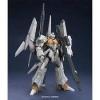
That's a great start! I keep seeing the RB6 on the shelf at the local hobby shop and asking myself 'Shall I? Shan't I?' and if this thread continues like it has begun, I'll be back there next week with some cash!1 point
-
Having been told the news yesterday and working for Model Zone at the Bromley store in London, for anyone on here who has been in there and possibly who i may have met over the last few years, would like to say thanks for the support and contributions, its been good, enjoyable experience and i've learnt alot.1 point
-
Good luck to the staff. Regardless of how good we perceive them to be or not to be - losing your job is crap. Lets hope the locations arent bought up by Costalotta Bucks coffee or some other "do we really need another brand seling exactly the same as the others" chain. Jonners1 point
-
Hello basic painting of the bottom of the fuselage finished: comments welcome.1 point
-
I didn't ponder too long, as that way leads to a shelved model. I added some Signalbraun and a little white to the basic Lifecolor pot to give it a browner hue, and I think it's kind of worked... it doesn't look as green as it did before anyway I also masked off the wing-roots to get a nice clean demarcation, and also masked off the nose, which I sprayed later, trying to give it a slightly different "style" of edge, to infer the grafting on and subsequent painting of the cannon nose. I tried to keep it subtle though, as no painter would intentionally misalign the edges if you see what I mean I'll play around with the base shade a bit, and then put the RLM82 splinter on the wings & tail. Would they really have been hard-edge, or more likely soft-edged at this stage of the proceedings? Thanks for the effort John Meanwhile the tiny terror has been in the workshop, and the Xtracrylix RLM81 bottle has done a Lord Lucan. I've been trying to find it by looking at the workshop from the perspective of someone that's around 3'4", but haven't turned anything up yet, so it kind of forced my hand. Kids! EDIT: Just found it, and it wasn't the boy - I was maligning him unfairly based upon past performance!1 point
-
I've heard from a little birdy that OrangeHobby are releasing a 1:350 Batch 3 Type 22 in the near future.1 point
-
Here's an idea for Revell... provide decals for the special scheme, but also provide decals for the same aircraft as a bog-standard line jet either before or after it wore the special scheme. Everybody's happy! Just for the record, I'd always go for the bog-standard scheme.1 point
-
Moebius models have original series Mk I viper 1/32, Cylon raider 1/32 and classic Galactica 1/4105 coming soon. It's for the 35th Anniversary of the original series!1 point
-
Now that the wind has abated for all of five minutes, I have managed to get outside to prime the model. Halford's Red Primer was used to prime the entire tank, then once dry the barrel was gently slid out from position and coated in Humbrol Tank Grey aerosol to replicate the factory heat resistant primer used on the real vehicles. A coat of hairspray will ffollow then I will apply the camo via airbrush.1 point
-
And the almost finished lading gear (just need to touch up those tires a bit) that's all for now Thanks again for stopping in MH1 point
-
The late Triassic was enormous fun though! Of course there were some brilliant modellers even in those days but for many of us the dawning realisation fostered by people like Alan Hall (aircraft), Chris Ellis (AFVs) and Peter Hodges (ships) that you didn't have to finish the kit in the markings it came in and could even convert it into somethng that looked entirely different was very exciting and unleashed tides of enthusiastic bodging. (I even recall building a Deacon SP gun on a Matador chassis out of postcard because plastic card was unknown in my neck of the woods.) Almark have a very honourable part in that history. And, because there wasn't the wealth of brilliant research material there is nowadays, there were fewer rivet-counters out there to inhibit us!1 point
-
Supermarine Victor Mk XIV What if the Rolls-Royce Vulture engine had been successful and so RR abandoned development of the Griffon? The Supermarine Victor is a Spitfire with a Napier Sabre engine. Build thread here.1 point
-
"Early in the morning of January 4th 1967, Bluebird K7 skimmed across Coniston Water on its second run of the day through the measured mile. At the controls was Donald Campbell, (later Sir Donald) and as the end of the run approached, it was clear that the craft was travelling faster than it ever had before. To the immense relief of all, the craft shot past the end marker at 315.27mph, setting a new World Water Speed Record in the process. Subsequent examination of K7 showed that its fuel feed system was faulty, and could have caused the engine to flame out at any time. If this had happened at speed, the thrust necessary to keep the craft nose down in planing trim would have been lost, and could have resulted in disaster. When this was pointed out to Donald, his stoic response was typical: "Well, it didn't." Donald’s fortunes were resurgent. Backers, so long absent from his record attempts, were buoyed up with the swell of national pride, and floods of offers of sponsorship arrived to regain the Land Speed Record. A vehicle was designed by the Norris brothers to achieve this, named, naturally, Bluebird CN8. The vehicle was not wheel driven, as the LSR was now held by the Americans at 594mph, and as the record was now held by rocket propelled craft, it was considered to be beyond the reach of driven wheel technology. First, a rocket propelled vehicle was designed and even mocked up, then a jet propelled vehicle was proposed, subsequently revised to twin jet, to be powered by Rolls Royce turbojet engines. RR as a British company, were fully committed to the Campbell project, and donated six engines to the group, along with the necessary corporate backup and technicians to service them. Construction of the 42ft, eight ton vehicle began at Motor Panels Ltd in Coventry in July 1968, and the first test runs were carried out in December the same year. Although the design deliberately used the twin jets close together along the vehicle’s axis to combat asymmetric thrust problems, longitudinal stability difficulties were still encountered. A single fin was added to the design as it had been with Bluebird K7, this one sourced from a scrap Lightning jet fighter. The vehicle was annotated as Bluebird CN8A. Also, in line with Donald’s wishes, an ejection seat was fitted to the vehicle to enable rapid egress in case of an emergency. Donald, having already survived a high speed roll in one of the earlier Bluebirds, was not keen to end his life in similar circumstances. This led to problems with siting the steering wheel in a position where it would not obstruct an ejection, and in the end it was decided that the vehicle would be steered by pedals operating both the rudder on the fin and the front wheels, affording 4 degrees of lock. The cockpit was fitted with a grab handle on the right hand side, to stabilise the occupant whose left hand would be gripping the twin throttles. In February 1969 a series of test runs determined that although stability was now greatly improved, the wheels were incapable of biting into the salt flat surface which would be its track, and tended to allow the vehicle to crab. The wheels were subsequently redesigned with the distinctive “locomotive lip” to aid traction, and it is in this final configuration that Bluebird entered the record books on 30th March 1970, with a new World Land Speed Record of 616.23mph at the Bonneville Salt Flats in the USA. This record stood until Gary Gabelich’s Blue Flame reclaimed it for America in October of the same year. Although successful, Donald declared the driving experience “horrible”, and the vehicle was never run under its own power again. It was on permanent loan to the Beaulieu Motor Collection until Sir Donald’s death in 1987, whereupon it was transferred to the Coventry Museum of Road Transport where it currently resides alongside its British LSR successors, Thrust 2 and Thrust SSC." Here it is awaiting it's chance: Cheers, Dean1 point


This leaderboard is set to London/GMT+01:00