
Review Content
Showing topics in Aircraft Reviews, Kits, Aftermarket (updates/conversions), Decals & Masks, Reference material, Armoured Fighting Vehicle Reviews, Kits, Aftermarket, Diorama & Accessory, Reference Material, Kits, Aftermarket, Reference Material, Vehicle Reviews, Sci-fi & Real Space Reviews, Figure Reviews, Locos, Trains & Layout Reviews and Tools & Paint Reviews posted in for the last 365 days.
- Yesterday
-
Excellent review, Mike, thank you! Cheers, Mark
-
Hurricane Mk.IIB (40007) 1:48 Arma Hobby The Hawker Hurricane was one of Britain's foremost fighters of WWII, and although overshadowed by the more graceful and slender Spitfire during the Battle of Britain, it was a capable aircraft that was available in large numbers, and achieved more than its fair share of kills during the conflict. It went on to see service to the end of the war, but was relegated to less onerous tasks as technology leapt forward resulting in faster, more agile aircraft that came on stream on both sides of the conflict. The type originated in the early 30s and first took to the sky in 1935, despite the Air Ministry’s tepid reaction to monoplanes at the time, and it was an aircraft that set standards for fighters that followed it, being a monoplane with a predominantly metal airframe, retractable landing gear, an enclosed cockpit and of course the delightfully powerful and throaty Rolls-Royce Merlin engine. Compared to the Spitfire it was a little old-fashioned, starting out with a fabric-covered ‘rag’ wing that was eventually replaced by an all-metal aerofoil, and it was less aerodynamically streamlined, with a thicker wing and overall chunkier, blunt appearance. Although the wing was replaced by a metal aerofoil later, it retained the fabric rear fuselage and as such was able to have minor damage repaired quickly and easily, compared to the Spitfire that would have to go back to a repair facility for structurally insignificant through-and-through bullet damage. A fabric patch followed by a few coats of dope, and the Hurri would be back to the fray, which endeared it both to its pilots and ground crew alike. The Mk.IIB was equipped with an extra four machine guns in the wings, bringing the total for each wing to six, but reducing its top-speed, further so because the wings were also fitted with bomb racks. These hard-points could also mount underwing fuel tanks, extending the aircraft’s range by 100%, which sometimes led to a mixed force of Hurricanes undertaking interdiction operations with faster variants providing cover. By the time the improvements to the airframe resulted in the Mk.IIC, it was tasked with ground attack, taking out German tanks, which weren’t as easy to crack as first expected, because 20mm cannon shells would often ricochet off the frontal and side armour, and bombing a relatively small target such as a tank was a matter of pure luck, all while the enemy poured lead in your general direction. It was withdrawn from front-line fighter service at this stage of the war, as by then the enemy aircraft outclassed it in most respects, so it carried on in ground-attack, night fighter and intruder roles where it excelled, without unnecessary exposure to enemy fighters. It was succeeded by the D that mounted a pair of 40mm cannon in gondolas under the wings, increasing its offensive power appreciably, at which point it acquired the nickname ‘The Flying Can Opener’, adding additional frontal armour to the airframe that was exposed during the run-in to target. They carried on in that role until the Typhoon came into service, which could do the job faster and more efficiently without the worry of being bounced by enemy fighters that outclassed it. The Kit This is a new boxing of the new tooling from Arma Hobby, which was one that many 1:48 modellers had been waiting for, as their 1:72 kits have a reputation for excellent detail, with the inference being that in a larger scale the detail would be even better, and we weren’t disappointed. The kit arrives in an end-opening box with a sturdy tray inside that prevents the dreaded crushing in storage. The painting of a bomb equipped fighter flying through an uncluttered sky, and the decal options printed in side-view on the rear. Inside the box is a cardboard tray that contains three sprues of grey styrene, a clear sprue, a sheet of pre-cut yellow kabuki-tape masks, and an instruction booklet that is printed on glossy paper in colour, with colour profiles on the rearmost pages. Detail is everything we have come to expect from Arma, with crisp engraved panel lines, fine raised rivets, restrained fabric scalloping effect on the fuselage rear, and plenty of raised and recessed features that should result in a superb model if care is taken during building and painting. If this is your first Arma kit, you should know that they have a technique of adding stiffening ribs and stringers inside their kits, and they hide away their ejector-pins in places that won’t be seen, usually with a circle of tiny turrets around them. They are usually placed so that they can be left intact without affecting assembly, but if they do need to be removed, you’ll be advised in the instructions. Construction begins with the lower wing for a change, drilling out holes applicable to whether you intend to fit bombs or drop-tanks under the wings of your model. The holes are marked in red for tanks, and blue for bombs, which is helpful, and the diagrams are accompanied by a little explanatory text that advises that the bombs are only used for one decal option, whilst tanks aren’t used in any from this boxing, catering to those that might want to use aftermarket decals. The gear bay is created from a well-detailed section of spar that has a pair of retraction jacks and a pressurised cylinder applied to it, then has the remaining walls and their ribs mated to it and covered by the bay roof, feeding a brass-painted hose through the bay once completed. Attention then shifts to the cockpit for a moment, building the seat from four parts, which is supplied with decal seatbelts and is glued to the rear bulkhead for later installation in the cockpit. We return to the wing again, removing the drop-tank location points for all decal options, and cutting new holes in the wing leading edge outboard of the landing lights, inserting supports for the barrels and the landing light bays in the lower wing at the same time. The gear bay assembly is glued into the full-span upper wing, adding another short spar closer to the rear, then joining the two halves together. Now we learn why we didn’t build the entire cockpit earlier, as it is built in the space between the wings once they are completed, starting with the control linkage and frame, with the foot rests/trays over the top, and a small lever glued to a cross-member on the left. The cockpit side frames are painted and inserted at the perimeter, locating in slots in the upper wing centre, and these are joined by the rudder pedals on a central mount, and a V-frame that stiffens the assembly. The control column is built from three parts and includes the linkages that lead aft under the pilot’s seat, which is inserted last over the V-braces at the rear, locating on more slots in the upper wing. Flipping the wing over, a pair of rods are inserted into the bays, their location shown by another drawing that highlights them in blue. The instrument panel is next, with raised details depicting the instrument bezels and other switches, with a decal included for it and the compass that fits between two legs under the panel, which you are advised to cut into sections for an easier fit. It is glued into the starboard fuselage half with a pair of small pieces of equipment, with six more in the port side, and the option to pose the foot step on the exterior skin in the lowered position, which is a nice touch. There is also a decal for a pair of dials moulded into the fuselage sidewall. With that, the fuselage halves can be brought together, seams dealt with, and then carefully mated with the wings, taking care not to damage the lovely detail in the cockpit. If you plan on modelling your canopy closed, you should also cut away the rails as indicated in red on a scrap diagram at this stage to allow the closed canopy to fit firmly. The underside of the fuselage has an insert with the tail-wheel fairing moulded-in, and further forward, the central radiator housing has its core made from front and rear sections with the matrix texture moulded-in, and a circular insert with hosing, all of which is glued to the underside of the fuselage and covered by the cowling that is made from body, intake lip and cooling flap at the rear, locating in a shallow recess in the lower wing that has a horseshoe flange with fasteners to add to the detail. A choice of tail wheel inserts in the hole under the rear of the fuselage, adding a full-span elevator panel with separate flying surfaces that fills the recess in the top of the tail, fitting the two-part fin to a stepped lug in the fairing, and fixing the rudder to the rear, allowing all the tail surfaces to be posed deflected if you wish. The main gear legs are made from a strut with a retraction jack moulded-in, and another added to the rear, plus a captive bay door that fits on the outboard side, and a two-part wheel fitted on the stub axle. There is a choice of two styles of gun camera fairing in the starboard wing leading edge that uses two different parts, and your choice depends on which decal option you have chosen. There are clear lenses to cover the landing lights, and the clear wingtip lights have a recess in their mating surface that you can add some green or red paint to depict the bulb before you glue them in position, adding two short barrels to the newly drilled out gun ports outboard of the lights. The gunsight and a clear lens are glued to a recess in the cockpit coaming at this stage, taking care not to disturb it before the windscreen is installed. While the model is inverted, a pitot probe and crew step are added to the port underside, and a clear recognition light is inserted just behind the radiator, painting it a clear amber, with a chin intake made from two parts in front of the wheel bays. The rest of the work on the airframe is done with the model resting on its wheels (if you’ve fitted them yet), installing exhausts and mounting blisters in recesses in the nose cowling, a pair of glare-hiding strakes in a straight line between the exhausts and the pilot’s eyeline for two decal options, and an aerial mast in the spine behind the cockpit, cutting off the little triangular spur near the top, and removing the short post on the fin for all options in this kit. A choice of two styles of prop are included for the different decal options, using the same blade part, but substituting different front and back spinner parts, plus a washer inside the spinner that can be glued carefully to allow the prop to remain mobile after building. To close the canopy, part T2 is used, but if you intend to leave the canopy slid back, a slightly wider part is supplied, marked T3, with pre-cut masks provided for all options, as well as the wheel hubs and landing lights. As already mentioned, drop-tanks are included for this boxing, built from two halves that trap the location pegs between them, and have a small stencil for one side, even though they also tell you they’re not used for any options in this boxing. The instructions also show the bombs being built up from four parts each, along with their pylons, for use with two options. Again, if you are using aftermarket decals, the tanks and bombs may be of use to you. Check your references to be sure. Markings There are three quite different options on the decal sheet, each having a full page of colour profiles at the back of the instruction booklet, with letter codes corresponding to a table on the front page that gives codes for Hataka, AK RealColor, Mission Models, AMMO, Humbrol, Vallejo and Tamiya ranges, which should be sufficient for most of us, although FS numbers are also included for most colours to help you further. From the box you can build one of the following: Hurribomber BE489/AE-Q 'Butch the Falcon'. 402 Sqn., RCAF, Warmwell, February 1942 Z3171/SW-P 'Hyderbad City', 243 Sqn. RAF, Hibaldstow, Pilot F.Sgt. J C Tate, Winter 1941/42 Z3675/WX-B, 302 Sqn. PAF, Church Stanton, August 1941 Decals are by Techmod, which is a guarantee of good registration, sharpness and colour density, with a thin gloss carrier film cut close to the printed areas. Conclusion Another fabulously well-detailed model of this doughty fighter that shows amazing attention to detail, and deserves to be the new de facto standard in this scale. This back-dating of the variant helps to fill another gap in the range, which we hope will continue to broaden until everyone has the mark and sub-variant that they want. VERY highly recommended. Review sample courtesy of
- Last week
-
Love to know where to get any crew for this beastie. Absolutely nothing close in 1/35 for IJA crew or even soldiers??? Steve,
-
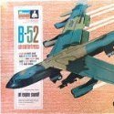
It is indeed a beautiful kit - I recently completed the Doolittle variant, and plan to build more (After, of course I build the new B-24H that Hannants is shipping to me at this very moment). Just a couple of minor comments: 1) Build it in the pretty much the exact order that Airfix recommends. Don't try to be cute, and put the horizontal stabilizers on before you finish the wings, no matter how good you think your Mk 1 eyeballs are. You'll be a lot happier, and save yourself tons of frustration in the process. Ask me how I know. You can build the various subassemblies up mostly out of sequence, but main assembly items should go in order, that's a biggie.... 2) I did use up all the available space in the nose for weight, but was unsure that it was enough, so I put additional weight inside the engine nacelles. After all, in the real aircraft, the engines are heavy and helped the real articles 'not be tail-sitters'. 3) Flip parts 32 and 33. The trim tab actuators for the horizontal stabilizers should be on top, and not on the bottom vis-a-vis the instructions. After I noticed this on actual Doolittle a/c, ( reference item 1, above) I started going over all the B-25 photos that I either have, or could Google. I found that not only did the -B models have the actuators on top, but so did pretty much every B-25 up through the final -J's. It's possible that a static restoration could result with incorrect items - for example the straight-winged Revell Lancaster, modeled after a static display not in flyable condition. At any rate, I flipped parts 32 on a second B-25, and the parts fit perfectly. FWIW...
-

Carrera Revell Dassault Mirage 2000C (03813) 1:48
Marcin Wojciechowski replied to Mike's topic in Kits
Mam zamiar zbudować ten model, ale zdecydowałem się przerysować linie na wklęsłe i dodać ślady śrub wykonanych nitownicą. -
Sd.Kfz.10 Zugkraftwagen 1t ‘Demag D7’ (SA72021) 1:72 Special Armour by Special Hobby In the decade before WWII, Germany was rearming - secretly at first - but overtly once they had publicly thrown off the constraints of the Versailles Treaty. In order to mechanise their military, many different vehicles were required, from large to small, with the Sd.Kfz.10 being at the smallest end. It was based on a hull rather than a ladder chassis, which gave it a low profile similar to that of a standard truck, despite it having a half-track running gear and a pair of steerable wheels at the front. It was powered by a 6L petrol engine from Maybach, and was intended to transport up to eight troops and tow smaller artillery pieces, which it did throughout the war, although production ceased before the end, despite a few attempts to re-vitalise the design. In its production form, the D7, it was capable of 40mph on road, although one of its main users, the Luftwaffe, limited it to 19mph to preserve the rubber trackpads, even though it was happy to cruise at a shade under 30mph. It had seven forward gears and three reverse, with a clever steering mechanism braking one or other track when larger steering inputs were made. It was demonstrated in 1938 and had entered service by the beginning of hostilities, with some further minor upgrades adding to its robustness and the added ability to tow heavier loads to increase its usefulness to the military. Toward the end of the war, proposals were made for an improved variant, but nothing came of it other than a few prototypes of one design, and drawings of another. The Kit This is another reboxing of the amended tooling that originated in 2011, but don’t let that dissuade you – it’s a modern tooling with lots of detail throughout. It arrives in a small end-opening box, with two grey sprues, decal sheet and A5 instruction booklet, printed in colour. The smaller sprue covers the revised idler wheels, drive sprockets, and more detailed tracks, which are an improvement over the originals that are still on the larger sprue, although the new tracks have some recessed ejector-pin marks on the inner face. Construction begins with creation of the track runs, which are based on a beam with axles moulded-in, onto which you slide the sets of wheels that are moulded in linked units for the two rear layers, and individually for the three outer wheels, plus the new two-part drive sprockets. The track on each side is moulded as a single run, and is wrapped around the wheels carefully, cutting off any spare links, then gluing the run in place. Take care when bending the parts, and warm them up a little to assist with flexibility. This is done twice as you’d imagine, and the completed runs are glued to the sides of the hull, with the crew area placed over the top, and firewall with windscreen frame moulded-in at the front of the area. There's a substantial sink mark below the windscreen, but this doesn't matter as it will end its days under the hood. You will need to provide your own windscreen from clear acetate, a piece of packaging material or even the front of a clear vacformed clamshell package, but they have included a template to assist you in this. It seems a little churlish not to include a slip of acetate sheet, but there you go. The bonnet/hood is fitted in front of the windscreen, with a nicely detailed radiator attached to the front. The front wheels are each two parts, and have a deeply dished hub moulded-in, as well as tread for the tyres. The axle is supported by a single lateral leaf-spring, steering arms and anti-roll bar that are put together and inserted into the wheel arch, with additional rods fitted afterward, their location shown from another angle in a scrap diagram. Number plate, towing eye, pioneer tools, width-marker lollipops and headlights are all clustered around the front, and inside the crew cab the driver controls, wheel and two seats are fitted, with a decal provided for the instrument panel. In the rear, bench seats, fenders, spare fuel cans and stowage boxes are assembled and attached, with the rear number plate and Notek convoy light at the back over a pair of mudflaps, and length of cable on a circular frame fixed on the back of the vehicle on three pegs, two of which are moulded-in. Markings There are four decal options on the sheet, which consists mostly of number plates, white stencils and the aforementioned instrument panel decal. From the box you can build one of the following: Sd.Kfz.10, unknown combat unit, Wehrmacht, Russia 1942 Sd.Kfz.10, Adler-built vehicle, unknown unit, Wehrmacht, Poland 1939 Sd.Kfz.10, Demag-built vehicle, unknown unit, Wehrmacht, Yugoslavia, summer 1942 Sd.Kfz.10, unknown combat unit, Wehrmacht, Czechoslovakia, May 1945 The decals are printed using a digital process and have good registration, sharpness, and colour density, with a thin gloss carrier film cut loosely around the printed areas. This means that the carrier film on their decals can be coaxed away from the printed part of the decal after they have been applied, effectively rendering them carrier film free, making the completed decals much thinner and more realistic, and obviating the need to apply successive coats of clear varnish to hide the edges of the carrier film. It’s a great step further in realism from my point of view, and saves a good quantity of precious modelling time into the bargain. Conclusion A welcome re-release of a lesser-known half-track from the early war, with a variety of camouflage options that should suit most folks. Highly recommended. Review sample courtesy of
-

ICM WWII British Aircraft Armament (48407) 1:48
Selwyn replied to Mike's topic in Aftermarket (updates/conversions)
Yes. Now Bs381c 224 Selwyn -

ICM WWII British Aircraft Armament (48407) 1:48
Troy Smith replied to Mike's topic in Aftermarket (updates/conversions)
AFAIK not made by any of them. A Tamiya mix is this https://mafva.co.uk/?p=2607 BS381C: 1930 COLOURS. Deep Bronze Green BS.24 Mix: 6 x Humbrol 3 + 3 x Humbrol 10 + 1 x Humbrol 2. Tamiya: 8 x XF5 + 5 X XF63 satin over. In use: 1934-39 then post-war from 1948. It was used on British vehicles, but the armament colour was not gloss. There is a Vallejo which is very close. https://alliedarmour1940.wordpress.com/vallejo-paint-mixes-for-british-armour/ Vallejo Model Color 24 (Deep Bronze Green) 70975 Military Green is just slightly lighter than the BS.381 standard (Mike Starmer, 2019) Description: Very dark yellow green – a rich black green. Same as the tank colour? BS 24? -
ICM WWII British Aircraft Armament (48407) 1:48
Selwyn replied to Mike's topic in Aftermarket (updates/conversions)
The colour used in British Deep Bronze Green Selwyn -
Also not a bad call.
-
You're not wrong. After looking at the Walkaround pics, I suspect I'll probably leave mine un-riveted TBH
-
Thanks for the review, Mike. I received mine today and love it. Another kit crossed off the bucket list. As for the rivetting or lack thereof, I'm glad ICM has supplied it in this clean form as the actual aircraft's rivets are very fine, indeed. I'll be riveting mine, but to my taste - fine and more prototypical - rather than relying solely on moulding technology and a possible fill and re-rivet. As far as I am concerned, it was a good call by ICM. However, each to their own taste. Ray
-
M3 Stuart Initial Production Interior Kit (35401) 1:35 MiniArt via Creative Models Ltd The M3 Stuart was designed before the US went to war, based upon the experiences of the British, which led to the US top brass deciding that their M2 light tank was obsolete. While the radial engine M3 was an improvement over the M2, it suffered from an underpowered M6 main gun at only 37mm, which although it was improved later in the war, the crews had to suffer with it for some considerable time. The British troops in Africa used it first against the superior tanks of the Afrika Korps, but fared badly in combat, suffering from the lack of range of the Stuart in the wide-open spaces of the African desert. It was fast and manoeuvrable however, and a British driver’s comment that she was a "honey" to drive led to one of its nicknames during the war. The M3A1 was an improved version that deleted the sponson mounted machine guns of the initial production, and some of these used more conventional diesel engines instead of the bulky radials, which gave the crew more room for other equipment. It also had a new turret with a basket for the turret crew to stand in, and no cupola for the commander that gave the tank a lower profile, and added a gun stabilisation system that helped with vertical alignment of targets while the tank was on the move, ironing out the bumps for the gunners. In British service it was known as the Stuart III and with the diesel engine version was designated the IV. It was hopelessly outclassed by Axis armour in Europe for tank-on-tank engagements, and was soon relegated to infantry support and recce roles, where it performed well. It was more successful in the Pacific theatre against the lightly armoured Japanese tanks in the jungle, where medium and heavy tanks could soon flounder in the mud and jungles. It continued to be used to the end of the war by the Allies in the Pacific area, although Russia, another user of the Stuart disliked it intensely and refused to take the upgraded M5 design that followed the M3A3. Variants were used well into the 60s, and Brazil even built their own version with redesigned upper hull and carrying a 90mm gun. Paraguay still had a few of its ancient original stock of 12 beyond the turn of the millennium, which is astonishing, considering the age of the machine. The Kit This is a brand-new tooling from our friends at MiniArt, which are producing an amazing output of new kits and partial re-tools in recent years, which is doubly-impressive given the situation in Ukraine over the last few years. This kit arrives in a top-opening box with a painting of an initial production Stuart on the front, clearly illustrating the prominent sponson-mounted machine guns that it shared with early variants of its stablemate, the M3 Grant/Lee. Inside the box are thirteen sprues in grey styrene, which is at variance from the sprue map, which shows twenty grey sprues, but this is due to some of the sprues being linked together on runners in our example. There is also a clear sprue, a fret of Photo-Etch (PE) brass in a card envelope, a decal sheet, and the instruction booklet, which is printed in colour on glossy paper, with profiles of the decal options on the rearmost pages. Detail is excellent as we’ve come to expect from MiniArt, and as this is an Interior Kit, you also get the complete engine and the entire crew compartment, for which the hull panels are detailed on both sides, although the interior has a few unavoidable ejector-pin marks, as they must go somewhere, after all! The running gear is similarly well-defined, and the tracks are supplied as link-and-length, taking the benefits of individual links and making the job a lot less labour intensive. Construction begins with the vehicle’s floor, laying out driver controls, foot pedals and other equipment, plus a choice of two styles of rectangular floor hatch, just in case you have a preference. The transmission and front axle assembly is made up from five sculpted and cooling-finned parts, which is then detailed with pivots, end-caps and linkages before it is installed on the floor, adding a short length of wire to link the assembly to a nearby conduit if you feel adventurous, then building up a box with a padded top, and two crew seats from base frame, cushion and back cushion, with a pair of PE lap belts wrapped around from the rear. The curved transmission armour on the front of the tank is detailed with various towing eyes, additional bolt heads that are cut from the sprue runner, and a central frame that can be folded from PE or replaced by a single styrene part. When it is complete, the interior face should be painted so that it can be installed on the front of the floor, locating on a trio of ledges with the floor inverted. The sloping drive-shaft tunnel is made from three main parts, adding a bottle to one side, a decal nearby, and a small grab-handle on the opposite side. This is lowered into position in the centre of the floor, with a small cut-out allowing it to fit over a transverse suspension bar moulded into the floor. A very busy engine firewall is based upon a rectangular panel with cut-outs, onto which a fire extinguisher and other equipment are installed, followed by a pair of radiator cores and associated hoses, plus a Thompson machine gun latched in place, minus magazine. The completed assembly is slotted vertically into the floor, which will later mount the radial engine on the opposite side, but first there is much more space to take up with equipment. A square(sih) stowage box with soft top is built and installed in front of the firewall on the left, a two-part instrument panel is attached to the transmission housing, applying three dial decals into the circular faces, making another diagonal panel from three-parts, with a PE dial in the centre, which then has a decal applied over it. The driver’s seat is emplaced behind his controls, fixing another box made earlier into position on the right side behind the bow-gunner’s seat, with another smaller box nestled behind that, and a pair of ammo boxes in front of the gunner for his immediate use in battle. Just because war isn't quite dangerous enough, a four-part jerry can is made and sited behind the driver in case they run short, although its usefulness might not yet be apparent because the fuel tanks are next to be made. First however, another small farm of boxes on a palette is made and attached at two points on the bulkhead on the right side, which even has a canteen flask attached to one side. Working on the engine bay now, the two fuel tanks are situated in the front corners of this area, with caps on top that can be accessed from the engine deck by removing two large armoured covers. Another tank is installed in the rear left of the compartment, adding various manifolds and hoses once they are in position before the curved engine support is slotted into the bay near the front. The Continental W-670 engine is next, with all seven cylinders moulded in this boxing, all of which have separate head parts, three pairs of which are linked by a narrow curved rod. A conical fairing is arranged around the forward end to duct the cool air from the large cooling fan, with a cross-brace and circular boss across the open space at the forward end. The fan is mounted on this boss, with a stub-axle on the outer face, with all the blades moulded into this well-detailed part. The tinwork is substantially different from an aviation variant of this motor, but the push-rods, intake hoses and ancillaries are similar, while the exhaust take-off doesn’t have the same constraints on it. The two exhaust manifolds carry the fumes from three and four pistons each, reducing to two larger pipes that end with a stepped joint to strengthen the join between it and the exhaust pipes. The intake manifold at the bottom of the engine is fed by two pipes that head up the sides of the engine, covered by a substantial engine carrier beam that also holds additional ancillaries, with the hole in the centre allowing more to protrude. More ancillaries including distributor and belt are layered over the carrier, with two tubular mufflers attached to the tops of the exhaust pipes, after which it is fitted into the engine bay, adding a cover to the top portion between the fuel tanks. Only now can the hull sides be fitted, but not before they are detailed with various parts, including electrical junction boxes, ammo boxes and other small parts, adding final drive housings to the front ends, using the bogie axle ends to locate the parts on the sides of the floor. The rear bulkhead is built with a hatch space in the upper half, with a dash-pot on the inside and a beam across the top edge, gluing it to the rear of the vehicle with the assistance of a scrap view from below. The rear hatch is in two sections, one of which has a PE clapping plate, both having handles, while the left door has a strange pot with a straw fixed to the inner face, and both doors can be posed open or closed as you wish. Above the hatch is an overhang with a PE mesh horizontal insert and styrene rear, with a couple of towing eyes mounted on the lower edge of the bulkhead. The next assembly is a thirty-cal machine gun, which has a cloth dump bag half moulded-in, finished by an additional part, and with an ammo box with a short length of link under the breech with a two-part mount. This is slotted through the glacis plate in a mount from the inside, adding a two-part instrument panel with five dial decals in front of the driver, plus a strengthening strap under the driver’s hatch. It is glued into position on the front of the tank, fitting the transmission inspection hatch with handle to the centre, and adding a pair of towing shackles to the front. The driver’s hatch is in two parts, and can be posed closed for battle, or with both parts folded open to allow the driver to see the full vista. A two-layer T-shaped cross-member is located over the upper glacis, adding a PE bracket that supports the open driver’s hatch, and a pair of bearing spacers to the final drive housings. As already mentioned, the earliest Stuarts had sponson-mounted machine guns, which extend from the main hull out over the tracks, roughly along the middle third of the vehicle’s length. The two parts are glued into position, and two .30cal machine guns are trapped between two-part mounts, one fitted to each sponson on a curved adapter with a three-part magazine that has a short length of link visible at the top. In the space behind the guns, boxes of ammo cans are stacked, leaving sufficient space for the two-part radio box in the left sponson, adding a length of power cord later in the process. A battery box is situated at the rear of the right sponson, adding a couple of grab handles, and inserting a divider between it and the flammable ammo storage. The sides of the sponsons can then be built around the equipment, painting the interior faces as you go, consisting of a short wall to the rear, a long panel along the side, and an angled panel with exit for the machine gun muzzle at the front. This is repeated for both sides, fitting two hatches to the front of the upper hull after adding an extra layer behind, a clear vision port, and openers to the sides. If you intend to pose the hatches up, you have the option of leaving the inclement weather inner hatches in position, which have large panes of glass and windscreen wipers to save filling the tank with precipitation. The open outer hatches are propped up with a pair of short stays from their top hinges. The hull roof is next, starting with the panel that has the turret ring moulded-in, adding rollers in housings to the underside, additional nuts on the top ring, and a pair of filler caps on the deck behind it, shaving away clasp details around them, and fitting a grab handle to one side. The completed part is lowered into place on the hull, adding a horn to the glacis next to the bow gun, including a small length of wire between it and the nearby bracket. Turning to the engine deck, four holes are drilled out on the diagonal deck panel to fit handles, gluing it in position and fitting a pair of rear lights on brackets to the sides, adding a little connecting wire if you wish. The main deck panel has a box added to the underside before it too is placed over the engine, adding a PE shroud to the forward edge to deflect incoming rounds or debris. Another PE bracket for one of the aerials is attached to the right, with another mounted on the side wall slightly lower and further to the side than the other. The aerial bases are each made from two parts, adding 73mm of stretched sprue, wire, or carbon fibre rod to represent the aerials themselves. A pair of dome-topped cylindrical airboxes are built from four parts each and attached to the rear of the sponson on brackets on both sides. We finally get some wheels for the bus, starting with the over-size idler wheels, which are trapped between two halves of the swing-arm, choosing one of two styles depending on where in production the tank fell. The idler wheels have PE rims glued on each side, building two of these assemblies, plus two more drive sprockets for the other end of the track run. The road wheels are mounted in two-wheel bogies, each one made from ten parts, building four in total, handed for each side. The road wheels flex-fit into position between the arms of the bogies, so that they can be mounted on the sides of the vehicle in shallow recesses along with the idlers and drive sprockets, with three return rollers on short axles above the main run. As discussed earlier, the tracks are link-and-length, using long single-part lengths under the wheels, individual links around sharp curves, and shorter lengths where the tracks are relatively straight. The various sections are attached to the sprues at the edges, and each short portion has a unique tab and slot format to ensure that parts can only be put together in the correct manner. There are a few ejector-pin marks on the inside of the longer track link sections, but these are raised and on flat surfaces, so shouldn’t be difficult to remove with a sanding stick or sharp blade, and won’t slow you don’t too much. When the track runs are suitably cured, fenders are added over the open areas, the rear straight sections fitted with a curved end to reduce kicked up mud, while the front section have inner side skirts to prevent mud ingress, which is improved further by gluing a PE web between it and the leading edge of the glacis plate, along with a PE stiffening strap further back. Before we start festooning the vehicle with pioneer tools, a pair of headlamps with clear lenses are placed, one on each fender protected by a PE cage, and both with a short length of wire leading back to hole in the glacis plate. To apply the pioneer tools you have two choices, the first and easiest method is to use fully styrene tools that have their clasps moulded-in. You can fit the same variety of tools to the rear of the vehicle removing the slightly raised location points from the styrene panel, and replacing them with PE clasps around separate tools that have no clasps moulded-in. An axe, pickaxe shaft and head, and a shovel are included, with a scrap diagram showing the finished area with PE clasps. More tools are located on the forward sponsons, with the same choice of moulded-in styrene clasps or separate PE fittings, which again have the raised marks removed first, with a completed diagram showing their locations once in place. The same process can be carried out for the single towing rope that the modeller must provide from either a 157mm length of braided wire or thread, fitting a pair of styrene eyes to the ends, and clamping it in place with PE brackets along the left sponson and fender. Now for the turret, starting with the main 37 mm M6 gun, the gun tube formed by a single part with hollow muzzle that is surrounded by a two-part frame, and has the halves of the breech closed around the rear, adding extra detail on the right, and a breech protector to the left side, followed by three-part pivots that are fixed around the gun without glue, then the coaxial machine gun is attached to the right side of the breech, and its ammo box is located on the left side, fed by a ‘bridge’ of link over the main gun in a guide to the breech of the smaller gun. The sighting tube is installed on the left with an adjustment wheel, pushing the barrel through the mantlet and inserting it into the front of the turret, which has been made from a well-detailed ring, with the faceted turret sides arranged around it after being detailed themselves. The roof has a yoke inserted on its underside in stowed or combat positions, and is glued in place, sliding the mantlet armour over the main and coax guns from in front. The commander’s cupola is similarly faceted, and each side is prepared by fitting a vision block in the slot, creating an asymmetrical hexagonal shape, and deciding whether to pose the turret crew’s vision ports open or closed. The commander's hatch is a flat panel with a lock on the upper edge, and hinges on the lower, which can be fitted open or closed, with more vision ports on the turret sides posed open or closed around the rest of the perimeter. Another .30cal machine gun is trapped between a two-part mount with adjuster handle, and fixed to a short column that is secured to the left side of the turret on curved brackets moulded into the surface. An optional two-part ammo box with a length of link can be fixed to the side of the gun, or if you wish to leave it off, an alternative stub part is supplied in its place. Before putting the turret into position, a few small parts are added under the gun near the hand-winding wheel for the turret. With that, the turret can be dropped into position to complete the model. Markings There are four decal options included on the small sheet, and you’d be right to guess that they are all in some variation of WWII Allied green, with only their individual markings to tell them apart. From the box you can build one of the following: Royal Tank Corps., British Army, Tactical Training School, Egypt, Summer 1941 2nd Armoured Division, Louisiana, USA, Autumn 1941 1st Armoured Division, Rock Hill, South Carolina, USA, Autumn 1941 Unknown Cavalry Regiment, Camp Funston, USA, Spring 1942 Decals are by Cartograf, which is a guarantee of good registration, sharpness and colour density, with a thin matt carrier film cut close to the printed areas. Conclusion It’s great to have this much detail present in a newly tooled kit of the diminutive Stuart, or Honey as the Brits called it, and it deserves to become the de facto standard for the scale. If interiors aren’t your thing however, just wait a little while and an exterior-only kit will be along shortly. Very highly recommended. Review sample courtesy of
-
I am very glad you did this review as I have been wondering what it would look like. And it looks like a great kit to be put into the stash. By the way, it is day one after the surgery for carpel tunnel on the right arm. I also had to have the elbow nerve worked on. Building can begin again in 4 weeks. And, thanks for the heads up on your experience with it. Great review as always.
-
Sd.Kfz.250/1 Ausf.B – Neue Ausführung (SA72005) 1:72 Special Armour by Special Hobby The Sd.kfz 250 was a light armoured halftrack similar in appearance to the Hanomag Sd.Kfz.251/1. Both were a mainstay of the German armoured Personnel Carrier fleet, but were flexible enough to also take up many other tasks. With two steerable wheels at the front, the rear was carried on tracks, giving it good clearance and rough ground capabilities that a truck simply could not manage once the going got tough. It was armoured sufficiently to deflect non-armour piercing rounds from small arms fire, but with an open top it was susceptible to both grenades and plunging fire, where the armour would concentrate the blast inside to the detriment of the occupants. Almost 6,000 examples were produced between 1940 and the end of WWII, and the vehicle was in service in time for the invasion of France, serving in most theatres in which the Wehrmacht fought to the bitter end. Fifteen official variants were produced, including ammunition carriers to support StuG batteries and signals cars that were equipped with radio sets. Other variants were equipped with heavy weapons that enabled them to provide infantry support. As a testament to their versatility, usefulness and durability, the type was sometimes reused when captured by Allied forces and insurgents taking back their homeland toward the end of the war, and they were kept in service for some period afterward where needs required. The Kit This is a reboxing of a kit that was originally released under the Mk.72 label, tooled for them by Special Hobby in 2013, although many new parts have been added to the series over the years, as can be seen by the differing style and colour of one of the sprues. The kit arrives in a figure-sized end-opening box that has a painting of the subject on the front, and the three decal options printed on the rear. Inside are four sprues in two shades of grey styrene, a sheet of decals, and the instruction booklet, printed in colour on glossy paper in A5 format. Bizarrely, the box states that PE and resin parts are included in the kit, which isn’t the case as confirmed both by contents and the sprue diagrams, so we removed the text from the box art. Construction begins with the lower hull, which is made up into a shallow dish from three sections so that the road wheels for the tracked portion of the vehicle can be interleaved behind the drive sprockets, which are both made from two parts each. The tracks are found on the sand-coloured sprue, and are shortened by five links to fit the chassis, as shown in the accompanying scrap diagram, and here a little heat judiciously applied might be beneficial to help the styrene wrap around the sprockets at the ends. The front wheels are each made from two halves, and these are fixed to the steering axle that is made up from six parts, with a wheel on each end. The crew compartments are made up next, starting with the driver’s compartment, which has much of the detail moulded into the floor, plus a dashboard with steering column and wheel, joined by two seat backs, control levers and two stowage boxes. The rear compartment is tread-plated in the lowest areas, and fixes to the back of the drivers’ section, with an additional seat, and a two-door cabinet at the rear, plus a stack of double drum mags for the machine gun behind the chair. The sloping centre sections of the body sides are glued in place on the lower hull after the interior is installed, adding a pair of towing hooks at the front, and the fenders with stowage boxes moulded into the surface, adding a stowage box in the space between the wheels on one side, and a barrel-shaped exhaust in the other. The upper hull is moulded as a single part, and is fixed on top of the centre section along with the rear bulkhead and a fold-down platform that stows near vertically in the left side, adding a fire extinguisher and more ammo toward the rear. The front armoured radiator cover, and crew compartment vision slots are fixed to the front, and a door, towing hitch, and two jerry cans in racks are added to the rear to complete most of the structural work. A mounting plate with an MG34 on pintle mount and a splinter shield are made and fixed to the front of the passenger compartment, adding another on a pivot at the rear of the compartment, then racking four Kar.98s on the sloped right side of the interior. A pair of wire cutters and an axe are fitted to the front arches, adding some slightly oversized width-indicator ‘lollipops’ to the corners of the wings and a convoy light to finish the build. If you’re a detail hound, we reviewed resin sets for the wheels and tracks some time ago that you can see here. Markings There are three choices on the small decal sheet, in service in various parts of the European theatre. From the box you can build one of the following: Sd.Kfz 250 Ausf. B (Neu), WH-1651812, Panzeraufklärung Abteilung 70, 4. Kavalerie Division. At the end of the war the vehicle was found in Mörtelsdorf, Austria, put out of service Sd.Kf 250 Aus. B (Neu), 388, WH-1629146, 3. Grenadier Kompanie, Panzer Grenadier Division Grossdeutschland, Lithuania 1944 Sd. Kfz 250 Ausf. B (Neu), 339, SS-900915, 3./SS-Pz. Aufkl. Abt. 11 - 11.SS Panzergrenadier Division Nordland (Schwedenzug - Swedish volunteers platoon), Berlin, May 1945. The vehicle was destroyed on the corner of Friedrichstrasse and Reinhardtstrasse on 2 May 1945. The crew including a Swedish female nurse volunteer were killed The decals are printed using a digital process and have good registration, sharpness, and colour density, with a thin gloss carrier film cut loosely around the printed areas. This means that the carrier film on their decals can be coaxed away from the printed part of the decal after they have been applied, effectively rendering them carrier film free, making the completed decals much thinner and more realistic, and obviating the need to apply successive coats of clear varnish to hide the edges of the carrier film. It’s a great step further in realism from my point of view, and saves a good quantity of precious modelling time into the bargain. Conclusion Another well-detailed Sd.Kfz.250 to add to the roster in 1:72, broadening the range, and adding some more esoteric decal options with a story behind them, as detailed in the accompanying text. Highly recommended. Review sample courtesy of
-
Do it yourself, you are plastic modeler od not? I have had the B-26-Marauder model on my table since yesterday. Great kit, with a few inconsistencies and questions about the correct coloring. But overall - the old Monogram kit is being retired...finally...
-
 Here you can see how it looks like on the model, including all other 787 parts from us.
 -
CR Models Boeing B747-8 Fans for Revell (CR144103) 1:144
RCI replied to Mike's topic in Aftermarket (updates/conversions)
-
CR Models Boeing B787 GE Fans for Revell/Zvezda (CR144100) 1:144
RCI replied to Mike's topic in Aftermarket (updates/conversions)
-
Thanks for the review. Hand pass. Saved me money.
- Earlier
-
US Army K-51 Radio Truck with K-52 Trailer (35418) 1:35 MiniArt via Creative Models Ltd The Chevrolet G506 truck formed the basis of a range of 4x4 load-carrying vehicles that could carry up to 1.5 tonnes of cargo, men or equipment. They were initially made under the 4100 code, then were renamed as the 7100 series, and usually had a standard enclosed cab, with a 3.9L straight-6 engine under the bonnet, and a four-speed “crash” (non-synchromesh) gearbox putting out a little over 80hp through all four wheels. It rapidly became the Allies’ standard light truck, and served in substantial quantities on the Western Front, with the Soviets on the Eastern Front, and the forces fighting Japan in the Far East. There were many variants, some in US Army service, others in USAAF service, with almost 50,000 of two specific types, the G7107 and G7117 sent over to the Soviets in large numbers under the Lend/Lease program. The G7105 variant was a fully-enclosed van-bodied truck that had a full metal bodyshell to protect the contents, and thanks to its twin wheeled rear axle, it was capable of carrying the same load as its open-topped siblings. They were used extensively by the Signal Corps, but are relatively rare in the overall panoply of chassis types for this series. Their low production quantities and participation in WWII trimmed their numbers further, so they are quite rare compared to others of the type, but some still survive of course, and can be seen occasionally at historic vehicle rallies and get-togethers of like-minded enthusiasts. When it is full of radio equipment and personal gear, a trailer expands its carriage capacity to include a generator or similarly heavy piece of kit. The Kit This is a new boxing of a recent G506 tooling from MiniArt, and is one of a large and still expanding range that is to be found in your favourite model shop. It’s a full interior kit, with engine, cab and both load areas included, along with some appealing moulding and detail, particularly in the cab, the equipment and those chunky tyres. It arrives in one of MiniArt’s medium-sized top-opening boxes, and inside are twenty-six modular sprues in grey styrene, a clear sprue, Photo-Etch (PE) sheet in a card envelope along with a short length of metal chain in a heat-sealed bag, decal sheet and glossy instruction booklet with colour profiles on the front and rear pages. Detail is excellent, and well up to MiniArt’s usual standards, using PE parts to enhance the model, and finely moulded details of the chassis, running gear, trailer, cab and interior areas. Construction begins with the ladder chassis, which has leaf-springs fore and aft, cross-braces and rear towing eye fitted to create the structure, then has the fuel tank with PE retention bands, PE rear bumper irons folded around a styrene jig, and axles installed on leaf springs, before the brake drums/hubs, battery and external brackets are added to the chassis rails. The transfer box and drive-shaft join the two axles together, and a steering linkage and box are inserted into the front of the chassis, then the engine is built up based on the straight six-cylinder block, with carburettor, dynamo and transmission added, plus the serpentine pulleys and fan at the front. The engine and substantial front bumper iron are fitted to the chassis, assembling the exhaust and its muffler, which slip into the underside of the chassis from below, held in position on PE brackets at the exit. The wheels are built with singles at the front, made from two parts each, and with twin wheels at the rear, again with separate outer sidewalls. Each wheel slips over its respective axle, with the hub projecting through the central hole. The three-part radiator housing is layered up, with the rear part having a hole that allows the air from the fan to cool the radiator when stationary, mounting on the front of the chassis and mating to the input and outlet pipes already in position. The crew cab is next, beginning with the firewall and forward sidewalls. The firewall is detailed with dash pots fixed to the forward side, and is set aside until it is needed toward the end of building the bodyshell, which is next. The sides of the van have a separate ribbing insert layered on the insides, to be joined to the floor after the raised platform for the crew seats is installed, fixing two four-part seats on top, and a small forest of levers in the centre of the floor. The floor is inverted to install the sidewalls, putting a short fuel filler tube on the outside that matches up with the extension within that leads to the tank. This boxing has a wall of radio gear assembled on the left side from a host of parts, and a long bench seat along the other with four cushions as a single part, with some impressive fabric sag moulded-in. Above the seats is a double cabinet with fake sliding doors, and PE chain straps at the sides, which is fitted near the rear along with a fire extinguisher on the right side. The rear light clusters are mounted on PE brackets on the rear of the side panels, one per side, and as is often the case with instruction steps, they may be better left of until after main painting. The rear valance plugs into the floor on two pins, joining the two side panels together on the lower edge. The dashboard inserts into the A-pillars that are moulded into the roof, with seven decals for the instruments and stencils on the glove box, plus two more on the headliner by the rear-view mirror, which installs into the front of the roof panel. The steering column is joined to the underside of the dash, adding a courtesy light, vent and six curved ribs to the inside of the roof in grooves. The rear doors and their interior cards are assembled with their handles, locking mechanism in a fairing with a flat PE surround, plus handles on both sides of the right door, and clear window glass with rounded corners. The crew doors and their interior cards are assembled with handles and window winders, plus the clear window glass that can be posed open or closed at your whim. The windscreen frame has the two clear panes fitted, and has a pair of PE brackets and styrene wingnuts that are installed either vertically for closed, or at an angle for open, with a scrap diagram showing the correct orientation of the various parts, and below it on the scuttle is a ventilator panel that can be posed open or closed as you prefer. The steering wheel is fixed to the top of the column, the diagonal kick panel is joined with the firewall and fitted out with three foot pedals, and a button that I think is the parking brake. The roof and firewall assembly are fitted to the growing bodyshell assembly with a choice of aerial bases on the roof in front of the vent cowling that sits on a PE base, while the rear doors are installed within the frame in the open or closed position if you prefer, adding a short stay from wire of your own stock, and two PE eyes on the corners of the roof nearby. Two rear arches are fitted under the floor into recesses, projecting past the line of the bodywork to encompass the twin rear wheels, then with the body righted, a pair of wing mirrors are glued onto the cab in front of the doors at handle-height on long struts with PE brackets at the bottom, posing the doors open or closed again as you wish. The body and chassis are mated, and a choice of cowling panels that fit to the sides of the engine compartment after adding a V-brace under the bonnet, then fitting the front wings that incorporate the section of running boards under the doors that joins up with the rear boards. The front of the vehicle has its headlights with clear lenses plus sidelights fitted to the wings, and PE windscreen wiper blades are hung from the top of the frame on styrene arms, then the front grille is built. You may have noticed that this appears on the sprues too for a simpler build process, but a more detailed and realistic grille can be fabricated from the PE parts on the fret. It is constructed completely from PE, and two styrene jigs are included on the sprues to assist with accurately creating the correct shape. The lower rail, light cages and curved side panels are made up on one jig from a single piece of PE, while the centre panel is folded up on another, then they’re joined together ready to be attached to the front of the engine bay. There are two PE brackets stretched across the front of the radiator, but if you elected to use the styrene grille, this process is condensed down to nipping the part from the sprue, cleaning the sprue gates, and gluing it to the front of your truck, removing a small curved section from the left of the styrene grille as it is glued in place. The bonnet can be fitted open or closed with a PE stay that is provided in the centre of the panel for the open option. Two additional stowage boxes are built out on the sides of the truck, with separate doors, PE padlocks, and a plate on the top to protect it from damage, one of them having a pioneer tool rack applied to the rear side, which has PE clasps and styrene tools provided to complete the details. It is attached to the right stowage box, and has a wire reel made up and fixed on a pin in a hole behind it, adding a choice of aerials and their tie-downs on the roof, varying depending on which aerial base you installed earlier. A small PE strap stops the roll unreeling during transit, just like the real (reel?) one. K-52 Trailer During WWII, the US used two small two-wheeled trailers for transporting additional equipment and other essential stores around the battlefield, towed by trucks and other vehicles that had at least a ¾ ton payload carried internally. There were two major variants, one for carrying many types of equipment and designated as G-518, the other a specialist water carrier that was given the catalogue designation G-527. The main contractor was Ben-Hur Manufacturing Co., which garnered it the nickname ‘Ben-Hur Trailer’, and its 1-ton load capacity in 3.2m3 volume meant that it saw a lot of action, mostly ignored by war historians and modellers alike, as it was a transport and not as interesting as the things that went bang. Nevertheless, there were over a quarter of a million built, and many of them spent their days dutifully following a Chevrolet truck around the roads and tracks of Europe and the Far East. This is a derivative of a new tooling from MiniArt, launched just after the G-527 Water Buffalo we reviewed recently, this kit has excellent detail as usual with MiniArt, including a full chassis, well-rendered chunky treaded tyres, and even a set of slat extensions to the sides of the structure with moulded-in wooden texture. Construction begins with the bodywork, starting with the two sides that have leaf springs moulded-in, which have the axle retention bolts added to both sides, PE tie-down loops down the sides, and the light cluster that is fitted on a PE bracket next to the rear suspension mount. A choice of external framework to the sides with or without the extension slats is glued to the sides, including small PE brackets at both ends of the slatted sections. The wheels are built from two parts, the larger having the outer hub, tyre carcass and the tread moulded as one, the smaller having the opposite sidewall details moulded-in. They are then put to one side while you build up the rest of the load area. The two sides are mated with the floor part, adding brake actuators underneath and on the side, and bringing in the ends to create the load box, with more PE brackets and foot stirrups to aid entry. While the chassis is upside down, the two-part inner hubs are fitted to the ends of the axles, adding a short length of 0.5mm wire to each one, and another length to a bracket under the floor. The towing frame is made from two converging lengths, which are fixed under the front of the floor on a pair of U-bolts, while a pair of mudguards are mounted on the chassis sides on pegs, inserting the wheels into their wells. The load bed is populated by a large generator that fills most of the area with a storage box at the front, which is first to be mad, including a PE padlock for security. Four jerry cans with PE straps are made with spare fuel to power the generator, starting work on the rear face where the control panel is located, which can be posed open or closed. The open option involves two PE door sections, the largest of which is the door that pivots up and slides into the housing with a styrene handle that is also found on the styrene closed door. Seven PE wingnuts are inserted between dividers for power connectors, which will still be visible when the main door is closed, exposing the wingnuts. This is fitted as one end of the generator’s cowling, adding another to the other end, and gluing PE handles between the columns of louvres on the sides, plus a pair of styrene tie-down loops. The opposite end has a radiator core mounted in the centre, and the top cowling has curved edges, and four more PE grab handles, a lifting eye, and a filler cap on the rolled edge. The tailgate is completed by adding the PE retaining pins on chains at floor level, then the two-part towing eye is mounted atop the front of the A-frame, and a jockey-wheel is built from two halves plus a yoke and pivot, with an alternate all-steel wheel if you prefer. This can be fitted under the hitch in either horizontal position for travel, or vertically for a parked trailer, locking it in place between two halves of the pivot. Another longer length of wire is fitted under the left chassis rail and hitch frame, dangling the end down over the hitch, adding a plug for the electronics, which has a hole moulded-in for the wire. The safety chains are cut to length, and are each trapped between two halves of their bracket, adding the hook on the loose end after drilling a hole in the part first. For protection of the equipment in bad weather, a tarpaulin cover can be made from five sides, adding PE clasps to the opening end, straps to the front, and short lengths of wire to represent the bungees that hold the tarp down around the lower edges. If you elect not to cover the generator with a tilt, the stowage box, generator and four jerry cans are installed on the floor, strapping a spare tyre under the chassis on a PE frame, which is held in place by a small hook at the rear. A third choice involves a slatted extension to the trailer’s sides, adding PE brackets to the sides earlier in the build, and fitting front and rear slatted sections to the front and rear, topping off the vertical sections with curved supports for the tilt when fitted. Markings There are five decal options on the sheet wearing green, including 1one in British service that has black camouflage over the top. From the box you can build one of the following: British Forces Radio Station, 8th Army Sector, Italy, October 1944 1st Armoured Division, 829th Signal Battalion, North Africa, Spring 1943 102nd Infantry Division, ETO, Autumn 1944 US Marine Corps, 4th Marine Division, Pacific 1944-5 Corps Signals Unit, 2nd Polish Corps, Italy 1944-5 Decals are by Cartograf, which is a guarantee of good registration, sharpness and colour density, with a thin matt carrier film cut close to the printed areas. Conclusion This is an interesting variant of the G506 chassis doing the job that many of this type were built for, and with the addition of the trailer it looks substantially different from its siblings, which with the detail that MiniArt pack into all their kits, it’s a very tempting offering. Highly recommended. Review sample courtesy of
-
Looks like a fun kit to build and detail, looking forward to watching the process @ABeck!
-
Looks like a great kit, but I'm still miffed that ICM doesn't replicate the rivets. You can argue and say that the rivets theoretically wouldn't be visible to the human eye in 48th scale, but I would say that this is incorrect in real life. Anyway, rivets makes the kit seem more detailed and real, so I'm hoping they will start adding them soon.
-
Just a question (not more !!!!!): Is this really the correct angel of incidence for the wing on the wing root? Another 3.5° to be added for the F/G ? EDITED1: Angel of incidence is 3.5° with kit parts! so no bothering
-
Looks nice. It's interesting that there was never a solid nose version of the Marauder like there was with the Mitchell, Havoc and Invader.


.thumb.jpg.0bc57cb4bb3dec8e063e1951db6690c2.jpg)


-
Forum Statistics
239.1k
Total Topics4.1m
Total Posts -
Member Statistics
34,517
Total Members3,626
Most Online
-
Who's Online 150 Members, 3 Anonymous, 713 Guests (See full list)
- LDSModeller
- 303sqn
- Heather Kay
- Delta Tango
- malpaso
- Giorgio N
- Teeradej
- gunpowder17
- 100SQN
- I Dole
- Potsie
- Dogsbodyx
- Casey
- Jari Lehtonen
- Reini78
- prowler93
- Zephyr91
- Itzdarkmatt3r79
- speedy
- Gustavd
- mini71
- Diego
- 2996 Victor
- Arie Vos
- Motty
- IanC
- Laurent
- RidgeRunner
- RevDWC
- Pritch
- Marlin
- Vanroon
- wimbledon99
- Mr T
- Robert
- Howard M
- alex_us
- trickydicky210
- Coors54
- mick
- Bruno P
- stever219
- Alex Gordon
- klubman01
- sprue
- Pat55
- beefy66
- brianthemodeller
- Aww94
- Hornet133
- Pete Field
- galaxyg
- Terry1954
- DavidB
- Antti_K
- Sabrejet
- rtfxwp
- Culham
- ScanmanDan
- Nick80
- colossusfr
- TeeELL
- Josh
- Malc2
- Fuoritema
- Nigel Bunker
- Mark Proulx
- Vultures1
- Rob K.
- Stefan Buysse
- Sergii
- dragonlanceHR
- rafalbert
- Walt1957
- Johnson
- Modelu Chris
- Tim R-T-C
- KRK4m
- SleeperService
- Stirtard
- cmatthewbacon
- Delayar
- dromia
- Halberd Models
- GRK
- crvena petokraka
- Rakovica
- kiwitrogg
- Nerazzurri
- jenko
- Ventsislav Gramatski
- Wojtek2
- Borisz
- Karearea
- ModelingEdmontonian
- ruudster
- rockpopandchips
- Jon Bryon
- drake122
- ragnarec
- Sebastian _SJM
- Mike N
- Archelaos
- Richard Cawsey
- Latinbear
- Wayne Bull
- Canoner
- Andee
- steh2o
- obermartin
- Nick Belbin
- Enzo the Magnificent
- ForestFan
- Buridean
- paulsbrown
- John_W
- slippers
- FlatlandFox
- elger
- El Búho de Sevilla
- badger
- viper-30
- Bobby No Mac
- diablo rsv
- Corey in Colorado
- JOCKNEY
- Alun Gallie
- Wings unlevel
- Andrew Jones
- Nick Nichols
- Michael louey
- Rosco
- Scimitar F1
- Macki
- Flyingdutchman
- Josh G
- Middo
- Toftdale
- Pat C
- Ed Russell
- giemme
- Wez
- Dads203
- Dutchplanes
- erniewise
- JohnT
- Zsolt
- GP2705
- Sierra Mike Sierra
- Roman Schilhart