brianthemodeller Posted March 15, 2018 Share Posted March 15, 2018 (edited) A little help please... I am building the Airfix FG1 as if in the landing pattern (gear & flaps etc. down) but I cannot find a decent image to show whether the auxiliary doors (on the side and belly) would be open or closed. Any advice, please? Edited March 17, 2018 by brianthemodeller Correction to thread title Link to comment Share on other sites More sharing options...
huvut76g7gbbui7 Posted March 15, 2018 Share Posted March 15, 2018 Open. See here: 3 Link to comment Share on other sites More sharing options...
brianthemodeller Posted March 15, 2018 Author Share Posted March 15, 2018 Thanks for that - obviously an hour spent perusing t'interweb for pictures of Phantoms wasn't enough! Link to comment Share on other sites More sharing options...
xvtonker Posted March 15, 2018 Share Posted March 15, 2018 When the Phantom was on the ground and engines shut down the auxilliary intake doors would sit slightly open. XVTonker 3 Link to comment Share on other sites More sharing options...
huvut76g7gbbui7 Posted March 15, 2018 Share Posted March 15, 2018 3 hours ago, brianthemodeller said: obviously an hour spent perusing t'interweb for pictures of Phantoms wasn't enough! It takes at least three days as one always gets diverted by pictures of Buccaneers,Scimitars,Javelins and Sea Vixens 5 5 Link to comment Share on other sites More sharing options...
Dazza Posted March 17, 2018 Share Posted March 17, 2018 (edited) For those who may be interested... The Aux Air Doors on the FG.1/FGR.2 were always open below 210 KTS to provide additional air to the engines, above 210 KTS they would close but, would blip open when engine bay pressure reached +10 PSI above atmospheric, their scheduling was via the CADC. J79 engined F-4s were slightly different, firstly and most obviously, no upper aux air doors, just those on the belly, secondly, the aux air doors were controlled by gear selection, U/C down = doors open, U/C up = doors closed. Also, on J79 F-4s, when on the ground, if the engines were shut down or there was a sudden loss of electrical power the doors would literally slam shut, many ground crew have received serious injuries because of this and is why hydraulic ground locks were used. -Daz Edited March 17, 2018 by Dazza 4 2 Link to comment Share on other sites More sharing options...
brianthemodeller Posted March 17, 2018 Author Share Posted March 17, 2018 Thanks Daz - you managed to answer the question I was just about to ask! I've always wondered what they were for and how/when they worked. Sadly it means my inflight FGR2 is now inaccurate but I think I can live with it! At least the FG1 will be right... 1 Link to comment Share on other sites More sharing options...
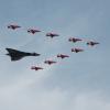
Roof Rat Posted March 17, 2018 Share Posted March 17, 2018 Great subject brianthemodeller you cant beat a good F-4 especially a EDSG/W one , and nice technical info from Daz. Just a couple to help you on your way. RR 5 Link to comment Share on other sites More sharing options...
71chally Posted March 17, 2018 Share Posted March 17, 2018 9 hours ago, brianthemodeller said: Sadly it means my inflight FGR2 is now inaccurate but I think I can live with it! Not necessarily, there are pictures of FG.1s/FGR.2s in flight with these doors open, but guessing at either low airspeed or high power. It might be unusual but not an unknown. I was told by someone who used to work on them that the upper auxiliary doors were spill air outlets. Is this then wrong and if they are inlets, how did they feed into the engines? 1 Link to comment Share on other sites More sharing options...
brianthemodeller Posted March 17, 2018 Author Share Posted March 17, 2018 3 hours ago, 71chally said: I was told by someone who used to work on them that the upper auxiliary doors were spill air outlets. Is this then wrong and if they are inlets, how did they feed into the engines? Probably my incorrect terminology... makes more sense that they were outlets not inlets. I’ll change the thread title to avoid further confusion! Link to comment Share on other sites More sharing options...
71chally Posted March 17, 2018 Share Posted March 17, 2018 Don't do that Brian as that could be right, it was a genuine question to somebody who might know better than myself. Link to comment Share on other sites More sharing options...
brianthemodeller Posted March 18, 2018 Author Share Posted March 18, 2018 11 hours ago, 71chally said: Don't do that Brian as that could be right, it was a genuine question to somebody who might know better than myself. Compromised and changed it to Auxiliary Air Doors - no reference to whether is going in or coming out! Link to comment Share on other sites More sharing options...
Dazza Posted March 18, 2018 Share Posted March 18, 2018 18 hours ago, 71chally said: I was told by someone who used to work on them that the upper auxiliary doors were spill air outlets. Is this then wrong and if they are inlets, how did they feed into the engines? There is often some confusion over the function of the Aux Air doors, the following is a summary of the info available from the USAF -1/USN NATOPS/RAF AP101 flight manuals. Put simply, the Aux Air on both J79 and Spey engined F-4s serve the same purpose, they provide additional cooling air at low speed and dump excess engine bay pressure when it exceeds engine bay pressure design limits, the main differences are, as I noted in my previous post, that the Spey engined FG.1/FGR.2 have the additional upper Aux Air doors (also called Ejector Doors) and are scheduled by the CADC, whereas J79 engined F-4s relied on the U/C up or down position. The excess pressure dump function was simply the pressure overcoming the hydraulic pressure of the actuator, once pressure is relieved, the actuator pulls the doors closed again, hope this helps clear things up a little... -Daz 2 1 Link to comment Share on other sites More sharing options...
canberra kid Posted March 18, 2018 Share Posted March 18, 2018 19 hours ago, 71chally said: Not necessarily, there are pictures of FG.1s/FGR.2s in flight with these doors open, but guessing at either low airspeed or high power. It might be unusual but not an unknown. I was told by someone who used to work on them that the upper auxiliary doors were spill air outlets. Is this then wrong and if they are inlets, how did they feed into the engines? James ( @71chally ) I hope this helps a bit to explain what's going on? John 6 2 Link to comment Share on other sites More sharing options...
71chally Posted March 18, 2018 Share Posted March 18, 2018 What I hadn't appreciated is that the doors cool the engine compartments rather than feeding extra air in to the engines. It doesn't get better than this does it, thank you chaps! 1 Link to comment Share on other sites More sharing options...
brianthemodeller Posted March 18, 2018 Author Share Posted March 18, 2018 1 hour ago, 71chally said: It doesn't get better than this does it, thank you chaps! Too true! One simple question and yet get a plethora of information that answers a dozen more. How much better could it be??? Many thanks from me too. 1 Link to comment Share on other sites More sharing options...
canberra kid Posted March 18, 2018 Share Posted March 18, 2018 Some nice drawings of the doors. and a nice drawing of what's going on upstream John 6 2 Link to comment Share on other sites More sharing options...
perdu Posted March 19, 2018 Share Posted March 19, 2018 brilliant info, thanks all Link to comment Share on other sites More sharing options...
Tailspin Turtle Posted March 19, 2018 Share Posted March 19, 2018 John - that's the best illustration of the inlet ramp function I've ever seen, although I will show the shock waves as straight rather than wavy lines. Thanks very much. Do you have one that shows the cooling air flow to the tail cone above the arresting hook? 1 Link to comment Share on other sites More sharing options...
canberra kid Posted March 19, 2018 Share Posted March 19, 2018 11 minutes ago, Tailspin Turtle said: John - that's the best illustration of the inlet ramp function I've ever seen, although I will show the shock waves as straight rather than wavy lines. Thanks very much. Do you have one that shows the cooling air flow to the tail cone above the arresting hook? I'll take a look Tommy, it could take some finding! As you can guess there is a lot of info to waid through. John Link to comment Share on other sites More sharing options...
Tailspin Turtle Posted March 19, 2018 Share Posted March 19, 2018 11 minutes ago, canberra kid said: I'll take a look Tommy, it could take some finding! As you can guess there is a lot of info to waid through. John Thanks - note that this air comes from the inlet at the base of the leading edge of the vertical fin and appears to exhaust out of two vents just above and abaft of the tail hook. 1 Link to comment Share on other sites More sharing options...
Mick4350 Posted March 19, 2018 Share Posted March 19, 2018 Another question about the aircraft. When the aircraft has the missiles that are connected to the underside that have no fins, what is the shade of blue on the device and are there any modelling paints in that particular shade ? 1 Link to comment Share on other sites More sharing options...
Ben Brown Posted March 19, 2018 Share Posted March 19, 2018 5 hours ago, Tailspin Turtle said: John - that's the best illustration of the inlet ramp function I've ever seen, although I will show the shock waves as straight rather than wavy lines. Thanks very much. Do you have one that shows the cooling air flow to the tail cone above the arresting hook? Tommy, Ron Downey just posted an F4H-1F flight manual in his Aviation Archives blog. There is a drawing that sort of shows the cooling air flow from the tail inlet on page 15 and a J-79 version of the air flow drawing John posted above on page 22. Ben 1 Link to comment Share on other sites More sharing options...
Phone Phixer Posted March 20, 2018 Share Posted March 20, 2018 9 hours ago, Mick4350 said: Another question about the aircraft. When the aircraft has the missiles that are connected to the underside that have no fins, what is the shade of blue on the device and are there any modelling paints in that particular shade ? Those "missiles" are drill Sparrows, commonly known as ballast Sparrows. As with all drill weapons, they were painted Oxford blue BS 381C 105. Some paint charts refer to this as roundel blue. Just a case of looking for those shades in the paint range available in your area. Rob. 1 Link to comment Share on other sites More sharing options...
Tailspin Turtle Posted March 20, 2018 Share Posted March 20, 2018 10 minutes ago, Ben Brown said: Tommy, Ron Downey just posted an F4H-1F flight manual in his Aviation Archives blog. There is a drawing that sort of shows the cooling air flow from the tail inlet on page 15 and a J-79 version of the air flow drawing John posted above on page 22. Ben Thanks Link to comment Share on other sites More sharing options...

Recommended Posts
Create an account or sign in to comment
You need to be a member in order to leave a comment
Create an account
Sign up for a new account in our community. It's easy!
Register a new accountSign in
Already have an account? Sign in here.
Sign In Now