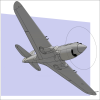
Giorgio N Posted February 4, 2016 Share Posted February 4, 2016 (edited) (Click here to see larger version of this image) If I didn't mention that it is a digital thing, would you think so? Really, I'd have believed it was a real model if you hadn't told, hard to believe it's all digital. Have to say that I'd like to see a plastic kit based on your fantastic work, it would put most commercially available kits to shame Edited February 4, 2016 by Giorgio N 1 Link to comment Share on other sites More sharing options...
Witold Jaworski Posted February 5, 2016 Author Share Posted February 5, 2016 (edited) I am in absolute awe. You may have already stated it but what on earth do you do for a living? Are you an Aeronautical Engineer or something! (..) Thanks a lot, Bruce! In fact, I earned my Msc in Aeronautics Engineering in 1994. However, I think that I did it because I am a dedicated aircraft modeller since I was ten!. (If you want to learn more about my projects, see here) Very interesting, although some of use say this has nothing to do with plastic modelling, what has been created can be saved such as a .STL file and printed on a 3D printer, and probably could be used in modelling Precisely! Thank you for this comment. The free (i.e. Open Source) program that I use for my models - Blender - can export and import the STL files. It also has some additional add-ons for 3D printer model optimisations. (As every real manufacturing process, 3D printing requires adaptation of such "general" models as mine). Really, I'd have believed it was a real model if you hadn't told, hard to believe it's all digital. Have to say that I'd like to see a plastic kit based on your fantastic work, it would put most commercially available kits to shame Thank you, Giorgio! Of course, the every real material imposes certain restrictions on the model. For example - in the plastic models you cannot recreate the skin thickness of the real aircraft, because there is a certain minimal thickness that you can create in the moulds. Thus every plastic kit is a kind of compromise between the real object and technological constrains. I will be really pround when somebody uses my models (they are free) as a geometrical reference for a new plastic kit! Edited February 5, 2016 by Witold Jaworski 1 Link to comment Share on other sites More sharing options...
Witold Jaworski Posted February 6, 2016 Author Share Posted February 6, 2016 (edited) Inside the Dauntless landing gear bay (which I cut out in the previous post) you can see fragment of the wing internal structure. Because I plan to create this model with retractable landing gear, I have to recreate these details. During this “general modeling” phase I will create here just the few key ribs and spars. I will show it in this post. The remaining details have to wait for the detailing phase.Examining the photos I identified two auxiliary spars and three ribs as the key elements of this structure: The spar is relatively simple to recreate. Initially I created a rectangle. Then I split it into six faces. Then I removed one of these faces, creating the space for the wheel bay:Then I added flanges, rounded corners, and the sheet metal thickness, to give this spar a more realistic look, as you can see in picture "a", below:However, when you examine this object, you will discover that the mesh of this spar is very simple (as you can see in picture "b", above). I obtained all these effects using a Solidify and two Bevel modifiers. It even did not require any special smoothing (I did not use the Subdivision Surface modifier here).In the same way I created the second spar:While working on these spars I also decided to recreate the wing skin that covered the gap between the main spar and Spar 1:It would be possible to shape such a hole by altering the wing mesh. However, if I already used the Boolean modifier in this object to cut the opening for the landing gear, it was much simpler to extend it for this purpose. Thus I extruded the whole leading edge section, up to the centerline. Then I cut out a part of this newly created surface using the modified “cutting tool” object that I used to form the landing gear bay (as you can see in the picture above).The mesh of the wing skin already contains a “rib” edge loop in place of the root rib (see picture "a", below). Thus it was easy to duplicate this edge into a new object, and extrude it by an inch into a flange. I offset this flange by a metal sheet thickness, placing it below the wing skin. (I did it by applying a temporary Solidify modifier — in Blender it produces better results than the Offset command). Finally I created faces between the vertices of the upper and lower rib edges (as in picture "b", below):As in the spar, the rib object uses a Solidify modifier to recreate the sheet metal thickness and a Bevel modifier to round flange edge. It also uses Subdivision Surface modifier to fit it tightly into the wing.A new rib that fits a trapezoidal wing segment requires somewhat more work. To create it, I prepared auxiliary “cutting tool”: two parallel planes (as in picture "a", below):I used this helpful Intersection Blender add on (I created it for similar purposes) to find the intersection of these two planes and the wing mesh. I separated the result of this operation — two edge loops (see picture "b", above) into new object. Then I continued as in the case of the previous rib: created the flange (see picture "a", below) and offset it from the wing skin. In this case I had to modify the bottom part of the rib, creating space for the wheel bay. Finally I created the vertical walls (see picture "b", below):In similar way I created another rib. You can see the result in the picture below:At this moment I am not recreating in this structure the lightening holes — I will obtain this effect using bump and transparency textures. I mentioned the “textured holes” many times in the previous posts. However, I will apply it much later, during the texturing phase. Thus, if you want to find more about this particular method, you can find its detailed description in Vol III of the “Virtual Aircraft” guide. (It is an introduction to materials and textures). In this source *.blend file you can check all details of the wing presented in this post.In the next post I will create the remaining elements of the wing. Edited February 6, 2016 by Witold Jaworski 6 Link to comment Share on other sites More sharing options...
Witold Jaworski Posted February 11, 2016 Author Share Posted February 11, 2016 In this post I will finish the “general modeling” phase of the wing, recreating the last missing elements. Of course, the result presented in this section is not the “final product”. It is just detailed enough for the next phase — applying textures and materials. (I will do it when I form the whole model). After applying the textures I will come back to this wing during the detailing phase, and recreate all its small details (like various small openings, aileron hinges, running lights, landing light, etc.).Finishing the wheel bay, I decided to add the rounded flange around its edges:I just did it because I do not like to see a non-realistic, “suspended in the air” edge of an opening. A part of this flange has to fit into the bottom of the fuselage. At this moment I left on that flange an “informal”, elevated fragment. I will fit it to the fuselage when it will be ready.There is another detail which is too subtle to be found on any scale plans. It is the shape of the landing gear leg bay, speaking more precisely —of its front edge:In the top view the front edge of this opening is a straight line, perpendicular to the aircraft centerline. Such an edge goes across several theoretical straight lines that you could draw on the bottom wing surface (see picture "a", above). This means that in the front view this edge forms a gentle curve.Initially I did not know if the Dauntless designers reproduced such a geometrically correct, but technologically more difficult shape. (Such a curved shape is more expensive because it requires additional formers for the wing skin panels and landing gear cover). I could imagine the situation when they decide to simplify this edge to a straight line. Fortunately, I have many high-resolution pictures of various restored SBDs. Photos of the landing gear confirm that this edge was curved (see picture "b", above).Another element I added was the solid rib that closes the center wing section. It is a standard Northrop solution for joining multicellular stressed-skin wing, designed in 1930 for their Alpha aircraft. Both wings were joined by multiple bolts evenly distributed around the airfoil circumference. The forces from the bolts were transferred to the wing skin via “L”-shaped flanges. You need to place a stiff rib between such flanges, because otherwise the whole structure would collapse. That’s why the rib closing the wing section is a solid, thick aluminum plate:I am not sure if I estimated properly the thickness of this rib. Anyway, I did it using a Solidify modifier, so it will be easy to alter this setting later. Because of this unusual thickness I am not sure if I will recreate the openings in this element (you can see them on the photo) using textures. The alternative method is to modify this mesh (it should be not very complicated, because it is a flat plate). During the detailing phase I will also recreate the vertical reinforcements visible on the photo.I started the bottom flap of the center wing section by preparing the auxiliary spar running along the flap hinges:As you can see, I also created the symmetric, right side of this wing section, using a Mirror modifier.The flap is created in the same way as the flaps of the outer wing panel. I separated the bottom part of the wing trailing edge into the flap skin. I added a very long, thin cylinder as the flap hinges. I copied the trailing wedge from the outer wing panel and placed it on the trailing edge:Then I copied the flap stringers from the outer flaps. In fact, I used just the cross sections of these original objects, extruding them into new stringers. I used Mirror modifiers to create the opposite sides of all of these spanwise flap reinforcements.In the next step I copied from the outer flaps the “standard” flap ribs (they all are clones that share the same mesh - see picture "a", below):Finally I modified the upper part of the center wing mesh, integrating it with the trailing wedge (see picture "b", above).When you open the split flap, you can see the internal structure of the wing:I studied the available photos of the flap bay in the center wing, then recreated the key ribs and spars:Finally I organized the whole wing into the appropriate hierarchy. At this moment the root element is the wing center — more precisely, its rear part:I placed all external wing elements on layer 1, while all internal parts are on layer 11. The auxiliary “cutting tools” used in the Boolean modifiers are in layer 9. To avoid “circular reference” conflicts I assigned the outer wing panel and the object that cuts its fixed slats to the common parent — the ”stiff” root rib.In this source *.blend file you can check all details of the wing presented in this post.In the next post I will start working on a more difficult part: the fuselage. 5 Link to comment Share on other sites More sharing options...
kev67 Posted February 11, 2016 Share Posted February 11, 2016 Very nice work, but very complicated for use mere mortals, even ones who have some 3D experience Link to comment Share on other sites More sharing options...
Witold Jaworski Posted February 11, 2016 Author Share Posted February 11, 2016 (edited) kev67, excuse me! I just could not resist the temptation to fill these empty inner spaces of the wing with some details! (A modeler's version of horror vacui ). In the next posts I will focus on the fuselage geometry. In fact, the overall process of creating such a detailed e-model has following phases: Preparation of the reference materials (most of the time: scale plans); Modeling of the main elements of the aircraft; "Painting": applying the textures (it includes panel seams and rivets, which are recreated using so-called bump maps); Detailing (during this phase I will create the landing gear or the cockpit interior); At this moment I am in the middle of the phase 2, and should not recreate all these wing internal details. (You can learn more about each of these four project stages here) Edited February 11, 2016 by Witold Jaworski 2 Link to comment Share on other sites More sharing options...
Witold Jaworski Posted February 13, 2016 Author Share Posted February 13, 2016 Before I start forming the mesh of the SBD fuselage, I will prepare an auxiliary object: the simplified version that will help me to grasp the general concept of its shape. I will describe it in this post.In the first step, I created the three key bulkheads:First one — the firewall — seems to have an elliptical shape:The contour of the station 140 on my plans is copied from one of the photos which I have found on the Vultures Row Aviation web site:For this conceptual shape I replaced the bottom part (after the trailing edge) with the curve extrapolated from the further tail cross sections.Finally, in station 271, which closes the main fuselage structure, I had to extrapolate its upper part:Then I extended between stations 140 and 271 a mesh, forming in this way the simplified tail (without the wing root fairing):I put another edgeloop in the middle of this tail to fit its contour in the side and top views.In the next step I recreated the mid-fuselage:In this concept object I entirely skipped the wing root fairing — because it requires a lot of work. I will recreate it directly in the final fuselage object. Note that the fuselage contours along the cockpit are straight lines. This detail is visible on many photos.I added in the middle of the cockpit another “bulkhead” edgeloop, and used it to determine shape of the bottom part of this fuselage:I fitted the contours of the fuselage that protrudes from the wing bottom surface into the contours in my reference drawings. It took some iterations to fit them. (The contour you can see in the bottom view was copied from original Douglas photo, so it is an important reference. The side view is not based on such a confirmed information). To preserve the straight edges on the cockpit sides, I had to move this central bulkhead along the fuselage centerline using the Edge Slide command. I was able to move or scale this edge only along the Z direction.Finally, when I finished this element, I checked if the cockpit sides are still straight, like before. They were not:As you can see in the picture above, I used an auxiliary horizontal plane set in the contrast color to see the effective shape of the fuselage mesh. I placed it just above the “longeron” edge that runs along the maximum width. The fuselage contour you can see on this plane is bent in the front of station 140. I think that such a shape is the effect of the “saddle”-like shape of the fuselage in this area. I am glad that I identified this issue on this simplified model. I will try to avoid such an effect in the final fuselage by directing all the lengthwise (“longeron”) edges along their real-life counterparts (upper-left to bottom-right on the side view).In this source *.blend file you can check all details of the model presented in this post.In the next post I will continue working on the fuselage. (I will use the object crated in this post as the reference). 6 Link to comment Share on other sites More sharing options...
Paroc Posted February 14, 2016 Share Posted February 14, 2016 Whoua, your job is incredible ! I like that it's courageous Link to comment Share on other sites More sharing options...
Witold Jaworski Posted February 17, 2016 Author Share Posted February 17, 2016 Paroc, thank you! I will do my best! OK, back to work: in the previous post I created a simplified model of the SBD fuselage that helped me to identify the eventual troubles in the modeling process. In this post I will create the mid-fuselage (more precisely: its upper part).I always try to think ahead about the mesh topology required for a given shape. In the case of the subdivision surfaces that are used here, this approach is extremely useful. When you place vertices of the initial bulkhead in the proper places, it greatly simplifies further modeling. To mark some “longeron” edges as “sharp” (Crease = 1), I started with a thin mesh “strip” instead of a single contour:As you can see in the picture above, it is built around the cockpit sides. Looking on the photos you can notice that one pair of the main longerons forms the side edges of the cockpit. It will be the upper edge of my fuselage. (The part below the windscreen seems to be a separate assembly, riveted over the longerons (see picture "a" below). I will create it later:I recreated the small fillet around the cockpit edge using two parallel edges placed close to each other (see figure "b" above). I could obtain similar effect using a single, partially sharp edge. However, in such a case the contour of this fillet on the fuselage cross section would have a shape that significantly differs from the circular profile in the real aircraft. What’s more, I will split these double edges at the rear edge of the cockpit opening. I expect that in this way they will help me to shape its rear, rounded corner.I extended the initial mesh strip from the firewall to station 140 (station locations — see previous post). After fitting vertices of this “bulkhead” edgeloop around station 140, I inserted in the middle of this mesh a new edge, just at the end of the skewed station 54. Then I removed the bottom fragment from the rear part of the resulting mesh:To avoid the curved contours of this mesh in the top view, I directed the lengthwise edges little downward in the second segment of this fuselage (see picture "a" below):To verify if the cockpit sides are really straight in the top view, I placed (on the tools layer – 10) many straight “stringer” probes (see picture "b" above). All of them are horizontal, arranged like the real longerons in the airplane (see picture "a" below):For the properly shaped surface, these probe objects should minimally protrude from the fuselage skin (as in picture "b" above). I used them to apply small adjustments to this mesh.When the cockpit sides are ready, I recreated the upper part of the station 140, and extruded it toward the cockpit. In this way I obtained the initial strip of the tail upper surface (see picture "a" below):It is relatively easy to prepare in this mesh a rectangular opening for the gun doors. The general rule of the subdivision surfaces is that their sharp edges (i.e. edges which Crease = 1) have the same shape as the free edges (for example — opening borders). Thus, if I incorporate into a smooth surface an area encompassed by sharp edges, I can later remove its inner faces without altering the shape of the outer mesh faces.But how to obtain a smooth surface around a sharp edge? It is simple: place it in the middle of a flat face of the control mesh. I did so. As you can see in picture "b" above, it is enough to make the three vertices on every bulkhead collinear. (In practice, small deviations from the theoretical line still produce acceptable results). You can learn more about this and other useful properties of the subdivision surfaces in Vol. II of the “Virtual Airplane” guide. In the next step I cut in this mesh strip the skewed rear edge of the cockpit opening:After removing the unnecessary vertices, I created a few new faces that finally joined this fragment with the rest of the fuselage mesh. As you can see in picture below, I also inserted another edgeloop just after the cockpit rear edge:This additional edgeloop and the few vertices in the corner control the surface curvature around of the cockpit opening. As you can see in the picture above, one of the resulting mesh faces has five vertices (so-called n-gon). In general, it is possible to decompose it into a triangle and a quad. However, I carefully examined the resulting surface and decided that this additional vertex does not deform in any way its smooth shape. Thus I decided to leave it “as it is”.Note that there is a single vertex in this mesh that controls the shape of the fuselage skin in the corner of the cockpit opening: I modeled it to resemble the original shape as I can see it on the photos. However, I will return to this fragment during the detailing phase of the modeling. With the cockpit canopy in place, I will then re-examine my photos and decide about the further details (for example — cutting the smaller openings for the ammunition feeders on the gun doors sides, which were introduced in the SBD-3).In this source *.blend file you can check all details of the model presented in this post.In the next post I will continue working on the fuselage. 5 Link to comment Share on other sites More sharing options...
HOUSTON Posted February 17, 2016 Share Posted February 17, 2016 Witold, I am totally amazed by your EXCEPTIONAL CAD skills and astounding research material that you have gathered . your work is SPECTACULAR ..albeit on a computer but all the same still excellent work. KUDOS... Link to comment Share on other sites More sharing options...
Learstang Posted February 18, 2016 Share Posted February 18, 2016 Amazingly detailed work, Witold! Even though Blender is easily available, your skills are not. Best Regards, Jason Link to comment Share on other sites More sharing options...
Witold Jaworski Posted February 20, 2016 Author Share Posted February 20, 2016 HOUSTON: I am happy that you have found this thread interesting! Thank you, I will do my best in the further post! Learstang: thank you! Well, I try to share all details of this "know-how" - in this guide. It is probably the thickest book about modelling ever written. (Because this is an e-book, there were no page count restrictions). . OK, back to work: In this post I will begin the wing root fairing and recreate the tail of this SBD fuselage. To be able to fit the fuselage to the wing, I started by creating a new set of the “bulkhead” edges. I placed them at the stations of the original bulkheads:In most airplanes the wing root fairing and tailplane fairing are created from additional sheet metal elements, fastened to the fuselage with multiple bolts. In the case of the SBD lineage — Northrop Alpha, Gamma and BT-1 — the wing root fairing was the integral part of the fuselage structure. (However, the SBD tailplane fairing had the conventional, “fastened” design).At the beginning I decided to form the rear part of the wing fairing as a separate object. In this way I will avoid the messing with the topology of the existing mesh. I will merge these two meshes later. Thus I copied into this new object a part of the fuselage mesh, and combined it with the initial part of the fairing cone:It is always worth to analyze how the modeled element was built in the real aircraft. Let’s look on the photos:On the picture above I marked straight lines in white, circular cross-sections in red and other curves in yellow. Note that the stringers connecting the circular sections are straight or gently curved. If you would think how this part was built in a workshop, it makes sense. It is not too difficult to recreate the circular cross sections of the fairing in the subsequent bulkheads. Then you have to set these bulkheads at the corresponding stations and connect them with the thin stringers. In this process you can always bent (a little) the initially straight stringer. That’s why all the lengthwise lines on the photo are straight or form a gentle curve.To ensure that I will recreate this shape properly, I placed three auxiliary stringers as they were located in the real airframe:Ideally, the outer edges of these test stringers should protrude a little from the wing root fairing surface. Using such them as indicators, I added new edgeloops in the middle of this mesh, and adjusted its bottom shape, fitting it to the wing:For the further work on the wing root fairing I need the tail. I extruded it from the station 140 up to station 271. Then I put one of the middle bulkheads at station 195 as a reference. Finally I adjusted the shape of this surface to the contours drawn in the side and top views. I did it using three new “bulkhead” edge loops, inserted in the middle of the tail:Evaluating the shape of this newly created part I examined not only the resulting surface, but also the control mesh. In the case of a fuselage, some geometrical problems are more evident when you check the flow of the lengthwise (“longeron”) edges. In this case I noticed that something is wrong with the last segment of the tail.The edge marked in yellow in the picture above corresponds to a real longeron on the fuselage. On the photos this longeron seems to be nearly straight. However, in the last segment of my tail its direction is altered:I re-examined my photos and concluded that I made mistake in the shape of the bulkhead at the end of the tail (station 271). The top contour of this bulkhead had larger radius than in my model. (However, I have an excuse: this part of the last bulkhead is an extrapolated shape, because its upper part is inside the tailplane — see the bulkhead pictures in the post where I started working on the fuselage. On these pictures you can see that I proportionally decreased width of the whole bulkhead contour. This deformation was the direct reason of this mistake). I corrected the tail shape, increasing the corresponding radii in the two rear bulkheads:Finally I modified edges around the gun door opening:I prepared horizontal edges of this opening earlier, while shaping the upper part of the station 140 bulkhead (see my previous post). Now I added another sharp edge that closes this opening. Note that for such a rectangular border I avoid crossing two sharp edges — because the resulting corner would create additional elevation above the smooth fuselage surface.In this source *.blend file you can check all details of the model presented in this post.In this file you can delete the vertices inside the gun door opening (as in figure above), and check that the shape of the fuselage around the gun bay remains unaltered. I “programmed” such a result into this mesh from the beginning. (I did it by appropriate adjustment of the few vertices in the first tail bulkhead).In the next post I will form the difficult, rear part of the wing root fairing. 4 Link to comment Share on other sites More sharing options...
Ace From Outer Space Posted February 20, 2016 Share Posted February 20, 2016 Hi Witold, this really is amazing work, incredible attention to detail. I for one have absolutely no issue with this being a virtual model, it is still a model even if it is not one you can hold in your hands. Excellent work sir, Cheers Viv 1 Link to comment Share on other sites More sharing options...
Witold Jaworski Posted February 25, 2016 Author Share Posted February 25, 2016 (edited) Hi Witold, this really is amazing work (...) Thank you, Viv! I will do my best! In this post I will finish the rear part (the most difficult in this aircraft!) of the wing root fairing. I started this fairing in the previous week. I previously formed the basic cone, up to the trailing edge. I created it as a separated object, to easier modify its topology. Now I copied into this mesh the further fragment of the fuselage, above the fairing (see figure "a" below): I also created a small rounded edge along the trailing edge of the wing (figure "b" above) (more precisely — along its closing wedge, as in figure "c"). This inconspicuous part plays the key role in forming of wing root fairing. First, I extruded it up to the station 140, then I inserted in the middle additional edgeloop. Then I could bent this fragment at will, by moving and sliding this middle edgeloop. I aligned this mesh patch to the wing fairing contour in the top view. Then modified its vertical shape, bending this mesh patch around the fairing cone: In the next step I extruded this patch from station 140 to station 195. I fitted its end to the bottom part of the bulkhead at station 195. Then I inserted in the middle two edgeloops (at stations 158 and 177). I shifted them on the planes of the corresponding bulkheads, fitting this wing root fairing to the reference cross-sections: When it was done, I extruded the bottom edge horizontally, to the centerline. I created in this way the bottom surface of the wing root fairing: While evaluating the bottom contour of the fairing in the side view, I realized that its shape depends on two factors. First of them is the fairing contour in the top view (because the trailing edge “slides” on the cone of the fairing upper surface). The second factor is the rounding radius of this trailing edge. To keep the bottom contour in accordance to the side view I had to decrease this radius a little (as in figure "a" below): After these adjustments, I cut out the corner of the fairing cone, adjusting it roughly to the shape of the trailing edge (as in figure "b", above). Then I slided this last edge of the fairing cone, fitting it to the upper contour of the trailing edge. Finally I joined these two surfaces by adding a few new faces: As you can see on the picture some of these faces have more than four edges. I left them in this state, because they do not disturb the smooth shape of the resulting mesh. (If I split them into a triangle and a quad faces, the triangles would disturb it a little). As I mentioned before, I copied into this wing fairing object large fragments of the fuselage mesh. I did it to better prepare this element for merging with the fuselage. Finally I did it: I removed all unnecessary faces and created the new ones between the fairing and the fuselage. Figure "a" below shows this new fragment of the fuselage mesh in yellow: Figure "b" above shows the resulting surface. In this source *.blend file you can evaluate yourself the model presented in the picture above. In the next post I will form the forward part of the wing root fairing. Edited February 25, 2016 by Witold Jaworski 5 Link to comment Share on other sites More sharing options...
fsssh Posted February 25, 2016 Share Posted February 25, 2016 Nice work Witold, Having just spent 2 months making 3d printed masters for a 1/16 'willys' jeep i feel for every vertex you are shifting around. I'm not sure what experience you have with the output from 3d printing but I just got my first set for this model through and my expectation of how the fine detail came out has been challenged, not to mention warping and difference in sharpness of detail between the top and bottom faces. I have done some 1/48 and 1/32 spacecraft in january and they were much easier.... some stuff i have worked on before for 3d printing is on my website www.markdodwell.com - (it's not a revenue raising website, i'm not soliciting for clicks!) i will be following this thread, really nice stuff. 1 Link to comment Share on other sites More sharing options...
Witold Jaworski Posted February 27, 2016 Author Share Posted February 27, 2016 (edited) fsssh, thank you! BTW: I have found an interesting show-reel on your page! (...)I'm not sure what experience you have with the output from 3d printing but I just got my first set for this model through and my expectation of how the fine detail came out has been challenged, not to mention warping and difference in sharpness of detail between the top and bottom faces.(...) Well, I have no practical experiences with 3D printing: I specialize in aircraft visualizations. However, I have read some books and other materials about various 3D printing technologies, and talked with the people who do it. My free models can be used as a starting point for the 3D printer models (as every technology, it has its own special requirements: you have to split the model into "printable" components, determine the thickness of the model surfaces and the "supporting structures", etc.) --------------------------------- OK: back to work: In this post I will recreate the forward part of the wing root fairing. Basically, it is a variable radius fillet. It starts just at the wing leading edge and transforms smoothly into the cone of the rear wing fairing:I extruded subsequent mesh segments of this fillet from the edge of the rear part of the wing fairing (from the point where I left it in the previous post). After each of these extrusions I decreased slightly the size of the last segment before extruding another one, obtaining in this way the variable-radius fillet:Initially these new segments are disconnected from the fuselage mesh, although I fit them to both: the fuselage and the wing surface.In fact the first two of these newly extruded fairing segments technologically belong to the rear part of the fairing. Thus I had to fit their surface to the three straight longerons that are there in the real airplane (I described details of this issue in the previous post):The panel that connects the rear and forward parts of the fairing had a straight upper edge. Of course, I recreated it in the mesh (you can see it in figure above).In the next step I merged these next three segments of the fairing with the fuselage:Note that I added another section (edgeloop) in the middle segment of the fairing (as in figure above) — just to fit it better to the wing surface. I did not want to extend it across whole fuselage, thus I terminated it in a triangle at the upper edge of this fairing. Surprisingly, such a triangle does not disturb the resulting smooth, concave surface.In figure above you can also see the auxiliary reference longerons, which helped me to ensure that this surface forms a straight line along their edges.To merge the most forward part of this fairing with the rest of this mesh, I had to add more edges to the fuselage:Each of these lengthwise fuselage edges “touches” the end vertex of corresponding fillet section. Once I placed them in this way, I removed the original fuselage faces and replaced them with the new ones. The right edge in each of these faces belong to the fairing:When I did it, I used an auxiliary plane to evaluate the resulting cross-sections of this fairing along the fuselage centerline. It seems that the presence of the adjacent fuselage faces in the control mesh deformed the circular sections of the fairing around wing leading edge. I decided to fix this minor deformation by sliding the last edge of this fairing outside:Finishing the wing fairing, I finished the main part of the fuselage:In this source *.blend file you can evaluate yourself the model presented in the picture above.In the next post I will form the bottom part of the fuselage (i.e. the part below the wing). I decided to build it as a separate object. Edited February 27, 2016 by Witold Jaworski 3 Link to comment Share on other sites More sharing options...
Witold Jaworski Posted March 3, 2016 Author Share Posted March 3, 2016 For this week I prepared the bottom of the SBD fuselage:The designers extended the SBD Dauntless fuselage below the wing, creating there a kind of the bomb bay. However, it was too shallow to house even a 500lb bomb (see figure "a" below). (The ceiling of this bay was formed by the skin of the center wing). There was a single mounting point inside, and the bombs were always partially hidden in the fuselage. When the airplane was not carrying any payload, the bomb bay was closed by covers (see figure "b" below). They were bolted to the flanges punched in the fuselage skin along edges of this opening:I suppose that in the future I will have to make some close shots of this area, thus I decided to recreate this detail “in the mesh”. This decision means that I cannot use the Boolean modifier to recreate this opening. In the effect, it will require much more work than similar details (like the landing gear bays) which I made in the wings. I will start working on the bottom fuselage in this post, and will finish it in the next one.In one of the previous posts I created a reference shape that fits the contours of this bottom fuselage in the side and bottom views. Now I have turned its layer on, to see this reference object again (in figure "a" below it is in red):I decided to create this part as a separate object — as it was in the real SBD. To begin, I copied the bottom part of the firewall into a new edge, and extruded it, forming in this way the first segment of the bottom fuselage (figure "b" above). Preparing for “cutting out” the bomb bay opening, I placed two sharp (Crease = 1) lengthwise edges in this mesh. They run along the opening borders (figure "c" above). To preserve the smooth circular cross-section of this body, these sharp edges are accompanied by adjacent, coplanar faces. (This is the same solution that I used for the rear gun bay opening in another post). These sharp edges will allow me to remove the faces from inside of this opening without altering the outer part of the resulting surface.After extrusion of these initial two segments I extruded four more, up to the flap hinge:I consequently marked as sharp the edges that follow the opening borders (as in figure "b" above).When it was done, I created the bomb bay opening by removing its inner faces. I also removed most of the faces from the rear segment, because I have to modify the mesh in this area (as in figure "a" below):In the view from bottom the rear edge of this opening had a circular contour. To recreate this effect I placed a quarter of 16-gon there (the symmetric side of this object on the picture is mirrored). Note the additional vertex at the external end of this “arc” — it helps to obtain a regular arc on the resulting curve. Then I projected (manually) the all six vertices of this polygon onto the reference body (see figure "b" above). Note also that the radius of this arc is a little bit bigger than in the bottom view on the reference drawing. After studying some photos I decided that it was slightly larger than on the reference drawing.In the next step I extruded the inner segments of this edgeloop into a new surface strip:Immediately after this extrusion I “flattened” this edge (by scaling it along the Y direction to 0), then adjusted its vertices on the XZ plane, fitting them to the reference contour. I also extruded forward the last vertex of this edgeloop, forming in this way the last straight segment of this opening border.Finally I created new faces, filling the gap between these new edges and the remaining mesh:Finally I created new faces, filling the gap between these new edges and the remaining mesh:When the central opening was formed, I extruded the tip of this body (the part below the flap — as in figure below):I will have to separate this tip later, because it was attached to the flap. To ensure that this separation will not deform the resulting meshes, I marked the future split edge as sharp (Crease = 1). Then I adjusted shape of this tip to its contours on the side and bottom views. Finally I created the rounded tip, by rotating its last “bulkhead” edge around Z axis. (Frankly speaking, I can see no special reason for the existence of such a tip. I can only guess that, beside the aesthetic reasons, its presence allowed to preserve a little more height in the rear area of the bomb bay space.I created the circular cut-outs for the wheel bays as in the wing — using the same auxiliary objects and additional Boolean modifiers (as in figure "a" below):Strangely enough, for this object the Boolean modifier works “in reverse”, and I obtained the proper effect using the “Union” (!) instead of the “Difference” mode. Once I did it, I adjusted the shape of the wheel bay flanges, fitting them to the bottom fuselage (as in figure "b" above).In figure below you can see the final object I created in this section:In this source *.blend file you can evaluate yourself the model presented in the picture above.In the next post I will continue my work on this assembly. I will recreate the covers for this opening, as well as their mounting flanges. 3 Link to comment Share on other sites More sharing options...
Witold Jaworski Posted March 5, 2016 Author Share Posted March 5, 2016 Sometimes the relatively simple shapes may require some substantial amount of work. In my previous post I created the basic shape of the bottom fuselage. It occurred quite complicated, because I decided to recreate the opening of the bomb bay “in the mesh”, instead of using the Boolean modifier. In this post I will complete the remaining details, enlisted in the illustration below:I started by forming the bottom part of the fairing along the wing leading edge. It is not as difficult as the upper fairing. To show you the basic idea I just added a new edge loop near the firewall, then I moved down the corner vertex downward. As you can see below, the resulting surface starts to wrap around the wing:Then I added another edge loop, adjusted locations of some vertices, and extruded fragment of this mesh in the spanwise direction:As you can see in the figure above (left) I hid the upper edge of this fairing below the lower edge of the upper fuselage panel. (You can see these overlapping panels on the close-up photos of the real aircraft).When I finished the wing root fairing, I recreated the bottom covers. I started each cover by copying the border edges from the adjacent meshes (as in picture "a", below):Then I adjusted these edges, matching the number of corresponding vertices. Once they were ready, I connected them with the strip of new faces as in figure "b", above).However, this cover was not completely flat! To fit it to the side view contour (and the reference shape) I inserted a new edgeloop in the middle of this mesh. Then I adjusted its height, fitting it to the contour of the fuselage:These removable covers were bolted to the flanges that extrude from the bomb bay edges. To obtain a better fit, these mounting flanges were stamped by the sheet metal thickness (as in figure "a", below):How do I form such a “depressed” flange? I started by extruding its borders (see figure "b", above). Then I connected these faces into a single strip (as in figure "a", below). Finally I extruded these faces (not edges!) along their individual normals (I shifted the extruded faces using the Shrink/Fatten command) as in figure "b" below:Finally I marked the outer edge in the control mesh as partially sharp (as in figure "c", above) to improve the profile of this flange.Figure "a" below shows the layout of the newly created cover panels. After all these modifications it is good idea to match this result against the available photos. As it often happens, I discovered that I should do it more often: there were some errors in this initial arrangement:Well, in fact I had to rebuild anew the side doors and the rear cover (repeating all the tasks depicted earlier in this post). You can see the final result in figure "b" above.Note that I slightly reduced the width (i.e. radius) of the rear cover. I decided that I was wrong estimating its size in my previous post. This time my reference drawing was right:Figure above shows the completed bottom part of the fuselage (I hid the removable covers). As you can see, there still are many small details that I have to recreate during the detailing stage.In this source *.blend file you can evaluate yourself the model presented in the picture above.The issue that I had with the bottom covers shows that I should do such a verification from time to time! In the next post I will “step back” a little and match the overall shape of this model against the photos. I will do it using a new method. 3 Link to comment Share on other sites More sharing options...
Witold Jaworski Posted March 9, 2016 Author Share Posted March 9, 2016 During the previous weeks I formed two main elements of my model: the wing and the main part of fuselage. As you saw, I could not resist myself for adding some details to the wing (like the ribs and spars of the flaps).Now I think that this is a proper time to stop modeling for a moment and compare the shape of the newly modeled parts to the real airplane. If I find and fix an error in the fuselage shape now, it will save me from much more troubles in the future! If I find an error in the wing shape – well, I will have more work, because I already fit it with some details which will also require reworking… You will see.The idea of using photos as a precise references emerged from the job that I did two years ago. One of my colleagues asked me if I can recreate the precise shape of the stencils painted on an airplane. He wanted to determine details of the numbers painted on the P-40s stationed in 1941 around Oahu. He sent me the photo. I started by fitting the 3D model to this historical picture, finding by trial-and-error the location and focus of the camera (as in figure below): Then I made the model surface completely transparent. I placed the opaque drawing (texture) of the large white tactical numbers on its fuselage, and the black, smaller, radio call numbers on the fin. I rendered the result over the underlying photo, finding all the differences. Then I adjusted the drawing and made another check. After several approximations I recreated precisely shapes and sizes of these “decals”.The key point in this process was to recreate the location and focus of the camera that was used to make the particular photo. Now I realized that it is possible to use the photos in the same way as precise references for my model. All I needed was a high-resolution picture.I decided to begin with one of the archival photos of the SBD-5 from VMSB 231, made in spring 1944 (the original photo below is 2127px wide): To find the camera projection that fits the model into airplane contours on the photo, you have to coordinate the location of the camera and its direction (I used for this purpose an auxiliary “Target” object). Yet another parameter to be adjusted is the camera lens length: The whole process is an iteration: I started from a rough first approximation (as in figure above). Then I enhanced it, gradually determining the ultimate camera and target location, as well as the focal length.In this process I based mostly on the elements which dimensions were determined by the “hard” evidence. It pays off that I placed most of the the fuselage mesh edges along the original bulkheads and longerons. (I will also benefit from this during further stages of my work). I was quite sure of the bulkhead stations because they were set according the original diagram. Thus I started by fitting to the photo the fuselage between the firewall (station 0) and the last bulkhead (station 271). Then I tried to find the proper camera focus that fits the middle bulkheads to the rivet seams and panel lines which are visible on the photo: I was also able to fit to this photo the root rib of the outer wing panels. However, I could not match the position of the wing tip! When I fit this tip to the photo, the fuselage deflection was wrong. Otherwise, as you can see (in the figure above) the wing tip of the model was a few inches below the tip on the photo. I started to wonder why I have such a problem…Figure below shows the best projection I was able to find. The fuselage bulkheads fit well the seam lines from the photo. It seems that the bottom contour of the tail was somewhat lower than in my model: The only weak point is the different elevation of the wing tip. I cannot say that it had a greater dihedral, because it was dimensioned on the original general arrangement diagram (7⁰ 30’ along the upper wing contour, in the front view).Finally I came to a hypothesis that what I can see on this photo is the elastic deformation (bending) of the loaded wing! This aircraft here is depicted in the flight, right? This means that these wings are carrying the load of about 4 tons of its weight. Their structure was stiff, but not absolutely rigid: every beam deforms (more or less) under the load. The airplane wings are not the exception: while flying in an airliner (like Boeing or Airbus) you can observe how their wing tips bend in the air. Of course, the relatively short, wide wings of the SBD Dauntless were much more resistant to such deformations. Nevertheless I think that we can trace the slight bending of this wing leading edge on the other shots of this airplane. For example, the white sun reflection on the photo in figure below allows me to reveal this dynamic deformation: We can see here the bending of the outer wing panel. However, there was another deformation: in its joint with the center wing. The root rib under loads slightly rotates around the wing chord, which elevates the wing tip even further (in figure "b", above). I supposed that the center wing was much stiffer (it had thicker airfoil and shorter span than the outer panels). Frankly speaking, this conclusion was a little surprise. I have not noticed such a deformation before — maybe because I was mainly focused on the WW II fighters? Fighter wings are the stiffest ones… Later, using other photos I ultimately determined that the Dauntless wings were as stiff as the wings of a fighters, thus their deformation in the horizontal flight was much smaller than I supposed in the picture above. (Its wing tips were elevated by less than one inch). Most probably the archival photo I tried to match earlier in this post has a strong barrel distortion, or was deformed in a different way when printed from the physical negative. Ultimately I decided to use some of the photos published by the Pacific Aviation Museum Pearl Harbor on flickr.com. It depicts an airplane on the ground, and was created using a digital camera. (It excludes the part of the eventual deformations that could occur during processing the physical negative). Figure below shows the result (I had to flip this photo from left to right because I modeled the left wing): As you can see, the wing perfectly fits its contour in this photo. I have found that the left aileron airplane was rotated upward by about 4⁰. I can see some differences in the hinge location of the upper wing flap (on the photo it seems to be placed at somewhat different angle, and shifted to the rear). The contour of the aileron bay also seems to be a little bit lower. On the fuselage you can see that the bottom contour of the tail is placed lower than in my model — confirming the observation form the previous photo.When you find deviations as these that I have found in the aileron and flap hinges, it is always a good idea to check them on another photo. Thus I fitted my model into a different picture from the same PAM photo stream on flickr: In this case I opened the wing flaps, because their straight contours helped me in precise positioning of my camera. It was possible to fit the bottom flaps to this photo (I just discovered that in this photo their deflection angle is 40⁰, while according to the specs it should be 42⁰). I was able to verify locations of their ribs and spars. (It occurs that these ribs, set according the stations diagram, are in the proper places). However, the upper flap did not fit properly into its contour in the photo. It was only possible when I shifted its hinge to the rear, placing it as in figure above. In this way I confirmed that these wing elements require corrections.After these initial findings I decided to verify both: the wing and the fuselage, to fix all the differences I would find. Of course, it required more photos. Matching the model projection to a single picture takes me several hours of work (usually — one evening). I assigned to each of these pictures a separate camera (as well as the camera target object). Their names are three-letter shortcuts of the source photo followed by the ordinal number: thus PAM-1 means “Pacific Aviation Museum – 1.jpg”, UND-1 is “Unidentified – 1.jpg” and so on. I think that these reference pictures will be also useful in the future stages of this work. Switching between these cameras requires several steps: you have to type the path to the corresponding photo, as well as to alter the scene renderer aspect ratio. To facilitate this operation I created a dedicated add-on, which allows me to switch between these pictures with one click: The ability to immediately switch between various reference photos definitely makes the difference! It encourages to study the same fragment from all possible sides. The photos can be extremely useful reference, but they do not replace the traditional scale plans. First you have to create a 3D model that is close enough to the real shape, using the plans. Then you can project such a model onto a high-resolution picture for the further improvements. In this source *.blend file you can evaluate yourself the model matched to the first picture from the Pacific Aviation Museum Pearl Harbor.In the next two posts I will write about the results of this verification. In the first one I will describe the errors that I found in the shape of my fuselage. In the second post I will describe the differences that I found in the wing. Sometimes fixing these minor errors require several hours of work… But this is why we are the modelers (“a slightly different human being” ). 4 Link to comment Share on other sites More sharing options...
hendie Posted March 9, 2016 Share Posted March 9, 2016 incredible research. Great catch on the wing loading in flight - that would have been so easy to overlook Link to comment Share on other sites More sharing options...
Witold Jaworski Posted March 12, 2016 Author Share Posted March 12, 2016 (edited) hendie, thank you for following this thread! In this post I will use the method discussed in previous post to verify the geometry of my model. It is a good idea to do it when there are no additional details. All the differences that I will find now will save me a lot of troubles in the future. For example — what if I would find that the base of the cockpit canopy in my model should be somewhat wider, when this canopy was ready? I would have to fix both shapes: the canopy and the fuselage. And what if I would already recreate the inner fuselage structure — the longerons and bulkheads — before such a finding? I would also have to fix them all. This is a general rule: the later modifications require much more work than the earlier ones! Thus I have to check everything when the model is relatively simple. You can compare the differences I will find in this post with the plans I published earlier in this thread: they contain various minor errors! Just as every drawing.Last week (see my post from 2016-03-09) I discovered that the bottom contour of the tail was somewhat lower than in my model:The main problem with mapping the tail shape was that its bottom part behind the wing was wide and completely flat. On every photo that I have the airplane is more or less deflected toward the camera, so the precise bottom contour of the SBD tail in the side view is an average of multiple estimations. That’s why it can be wrong on my scale plans! I also found a minor difference in the forward part of the fuselage below the wing. However, its forward part on the photo above is obscured by the truck. Nevertheless, I guess that the forward part of this cover it had a straight side contour, located minimally below than this contour in my model. To check this I mapped another photo of the firewall:This photo confirms my observations from the side view picture. Although the bottom of the fuselage here is lacking the bottom covers, the corner of their mounting flange “touches” the bottom contour of my model. It means that the real contour was somewhat lower, more or less along the yellow line that I sketched on this picture. However, you can see here another difference: the upper part of the firewall is little wider than the elliptic contour that I assumed (It seems that the shape of the firewall was not an ellipse, as I assumed in one of the previous posts).To make sure that this is not a mistake in the matching the model and the photo (or the effect of a barrel distortion), I also used another picture, from other restoration:The photo above confirms that the fuselage was little bit wider at the cockpit edges than it is in my model. The trace of the bolt seams on the wing reveals another difference: the wing root fairing was also wider (at least its forward part).To make sure that this difference is true, I have to find it on every photo that I map onto my model. Thus I mapped two other photos. They come from Pacific Air Museum. I can use them to verify the width of the mid-fuselage and the span of the rear part of the wing root fairing:The good news is that the maximum width of my fuselage perfectly matches the photo (a good luck!). I found that the width difference at the cockpit edges found at the firewall is (approximately) constant along the whole length of the cockpit (figure "b", above). It disappears behind the cockpit (i.e. in the front of station 140). The wing root fairing was somewhat wider at the trailing edge (figure "a", above).As usual, I used another photo to confirm these findings:Because this photo depicts the whole fuselage, I had to check these details using higher zoom factors. This photo confirmed what I have found in the previous one. In addition, it seems that the width of the fuselage in my model matches the real contour of the tail up to station 271.Once I confirmed all these differences, I had to fix my model.The wider wing root fairing behind the trailing edge can create impression of lower tail contour on the photos taken from the side (in the first photo in this post). This is because none of these photos is an ideal side view shot. In each of them the camera was located above or below the fuselage centerline. That’s why I decided to begin by fixing these differences in the fuselage width:Once they were corrected, I could fit the side contour, matching it to the horizontal photo of the tail:As you can see in this picture, I also minimally modified the upper contour of the fuselage. (Because the upper arc of its cross sections was looking like a part of a flat ellipse, while it should be a regular arc).Figure below shows the ultimate differences between the reference drawings I created several month ago and the contour obtaining from matching the 3D model to the photo:As you can see, nobody is perfect, so I also did some mistakes. However, I was aware that the bottom contour of the fuselage was a guess: I did not have any photo where it was directly visible. All the pictures were taken from below or above, leaving some space for various assumptions (which often results in some errors).Finally I fit the covers on the bottom fuselage (below the wing) to their contours in the photo:I moved slightly downward the forward part of these covers. As you can see in figure "a", above it was a relatively small difference. Initially I assumed that the cross sections of this bottom fuselage were elliptic arcs. However, in such a case, for the given width and height (from the side and bottom views), the edges of the wheel bays would appear a little bit lower than those visible in the photos. Thus I think that the contour of the middle cover in the front view had a slightly different shape (as depicted in figure "b", above).In this source *.blend file you can evaluate yourself the model from this post.While matching the model to the photo (PAM-3) taken from left side, I noticed slight differences in the wing rib shape: it seems to be a little bit thicker than on the picture. I will analyze this and other differences of the wing in the next post. Edited March 17, 2016 by Witold Jaworski 4 Link to comment Share on other sites More sharing options...
hendie Posted March 13, 2016 Share Posted March 13, 2016 I'm constantly blown away by the dedication not only to your model but in the depth of your research. For such minor dimensional differences, many people would have just accepted the error factor and moved on. Excellent work 2 Link to comment Share on other sites More sharing options...
Witold Jaworski Posted March 17, 2016 Author Share Posted March 17, 2016 hendie - thank you! In this post I will continue verification of my model by matching it against the photos. This time I will check the wing geometry.In the first photo from the Pacific Aviation Museum (in my model it is marked as PAM-1) I identified several differences:First I noticed that the hinge of the upper flap in my model is in the wrong location (I had to shift it forward by 0.7 inch). The upper edge of the aileron bay had slightly different shape on this photo. In this picture the tip of the aileron (the point lying on the wing tip outer edge) is located in the front of the corresponding point in my model. (The difference is less than 1 inch). Surprisingly, the inner (root) rib of the aileron seems to be a little bit higher in my model than on the photo. I can see also similar difference in the root rib of the outer wing panel. Location of the aileron bay upper edge on this photo can also be interpreted as located below the corresponding edge in my model. Does it mean that I made an error in forming this wing? The last visible difference are the outlets of the fixed slats. According the photo they were smaller and set at slightly different angle.To check the differences in the wing thickness and the details around its trailing edge, I matched my model to another photo:I opened the wing flaps to better match the projection of my model to this photo. I used the shorter edges of the flaps to precisely determine their deflection. The bottom flaps fits well into this photo (if you take into account that in the depicted airplane the outer flap is bent). To fit the upper flap I had to shift it by 0.8 inch, as shown in the previous photo (as in the first figure in this post). This confirms that there is a difference! What is interesting, the wing on this photo is also slightly thinner than in my model — which confirms that I made a mistake in recreating the shape of its ribs.As I wrote, I was convinced that I properly recreated the airfoil shape. I used the original coordinates of the NACA-2415 (and NACA-2409) airfoils (as you can see in figure "a", below)! Thus I used another, side photo (PAM-3) to check this finding:The overall chord of the wing rib in figure above seems to be OK (luckily, on this photo you can see the fragment of the leading edge between the truck forks). The chord of its bottom flaps in my model also fits corresponding chord on the photo. However, the upper edge of the root rib in my model seems to be too high (by about 0.3 inch). I can see clearly that it occurs in the middle of the upper flange of this rib. On the scale plans this difference corresponds to just half of the contour line width! That’s why we have to use photos: the drawing conventions alone make the scale plans not as precise as we wish… The PAM-2 photo reveals that this difference (maybe somewhat smaller than at the root) extends over the whole wing span.Well, so I had to fix it. While lowering the upper part of the center wing was relatively easy (figure "a", below), I had also to modify all the adjacent objects — ribs, spars, and the fuselageThe more difficult was to make similar modification in the outer panels. The difference was smaller at the wing tip. To preserve the straight lines of the spanwise mesh edges I moved the whole selected area down by 0.3 inch, then compensated the difference at the wing tip by small rotation around the wing root chord. (I had to separately rotate each of these “longeron edges”). Of course, then I had to make a lot of minor compensations in the upper flap and the aileron contours.However, I had to modify these trailing edge details anyway, following the other findings from the photos:In this modification I had to revert the changes I made three months ago to the aileron bay edge (in my post from 2015-09-12 about details of the outer wing panel). It was the wrong location of the flap hinge, while the aileron bay edge should be in the place depicted on the reference drawings! In fact, drawing these scale plans I assumed that the hinge of the upper flap was directly above the hinge of the bottom flap. (You cannot see the difference on the most common, horizontal photos). Now I know that it is shifted away from the auxiliary rear spar by about 0.8 inch. After this modification I had to shorten the chord of the upper flap and rotate its ribs and spars, adjusting them to the altered directions of the flap skin. It required a few additional hours...Once I finished with the trailing edge, fixing of the outlets of the fixed slats was easier. I just had to modify the shape of the “cutting tool” auxiliary object, used in their Boolean modifier:Then I adjusted the slat internal surfaces, fitting their upper edges to these modified openings (as in figure "b", above).If I encountered such surprises on the upper wing surface, what do I find on the bottom of the wing? I started by examining the outer wing panel:It was surprisingly difficult to find an appropriate projection for this wing — I badly missed the fuselage here! (It would allow me to better determine the proper direction of the camera). The barrel distortion of this photo could also have some influences on this matching. Fortunately, it seems that my model fits better this area of the real wing. The first difference I found was in the fixed slats: minor adjustment of their direction and sizes. I fixed them in the same way as their outlets on the wing upper surface (I will not bother you by describing the details). Another difference is more subtle: it seems that the real wing tip has slightly different shape than in my model!Of course, I had to check it on another photo, taken from another direction:This photo confirms my finding: it seems that I made another wrong assumption about the shape of the wing tip. (I assumed that the rear part was a single arc, while it is at least a smaller arc and an unidentified curve — maybe short piece of another arc of larger radius?). Of course I accordingly modified the wing tip (by adjusting location of a few of its vertices — in fact it was not as complicated as it sounds).For the complete verification of the wing, I used the picture from the SBD manual. I checked the bottom surfaces of the center wing:To speed up narration in this post, the picture above is showing the updated mesh. I just enlisted the modifications that I made. As you can see I had to adjust the outer edge of the wheel bay (because it was not a simple circle). There were some minor differences in the split lines of the bottom covers (I had to adjust the bottom fuselage! Again!). Ultimately, I discovered that I placed the fixed ribs above the flaps in wrong locations (I really do not know why I not followed the stations diagram— now I corrected this mistake).In this source *.blend file you can evaluate yourself the model from this post.This is the last post about this “great verification”. Now I am coming back to modeling. In next two posts I will recreate the empennage of this aircraft. 2 Link to comment Share on other sites More sharing options...
Witold Jaworski Posted March 19, 2016 Author Share Posted March 19, 2016 In this post I start to work on the tail assembly. The horizontal tailplane has similar structure to the wing — but it is simpler. Thus I started it in the same way as the wing, by forming its root airfoil:In the most of the aircraft the tailplane has a symmetric airfoil. So it was in the Dauntless. I did not find its signature (family) in any of the reference materials, thus I carefully copied its contour from the photos (its rear part — the elevator — seems to have modified shape, anyway). It has incidence angle of 2⁰, so I rotated the rib object and used a Mirror modifier to generate its bottom part.During this work I decided that I will use this rib as an auxiliary reference object for shaping the horizontal stabilizer. To precisely match the contour copied from the photos, I rotated part of this curve in the top view. Now it runs along the outer edge of the tailplane fairing:However, because I am going to copy this rib into the initial edge of the horizontal stabilizer, I already prepared three vertices for the leading edge of the elevator (as in the figure above).During this work I was struck by the idea that it is stupid thing to model the whole empennage, and then to verify it against the photos. The much better approach is first to “draw” in the 3D space their contours and match them to the photos, then to model their surfaces. In this way I can identify errors in my reference drawings before I start the modeling! The parts formed in this “verified” way and continuously matched to the references will have better quality!Thus I interrupted forming the horizontal tailplane, and quickly shaped another auxiliary object — the contour of the rudder and fin:What’s more, I decided to recreate in the model the basic reference “trapezes” of the fin and rudder. They are determined by the explicit dimensions in the general arrangement drawing, which I already used some months ago to draw the 2D reference drawings:While in the model space the 1 unit corresponds to 1 inch, I did not need to multiply every dimension by the scale coefficient. It was a big surprise when the trapeze drawn according these re-applied dimensions occurred shifted left by 0.7”!:I immediately did the same test for the horizontal tailplane. It also was shifted by 0.7”!:Well, such a coincidence suggest that I made a kind of systematic error in calculating locations of the elevator and rudder axis for my scale plans. Most probably there was something in their extremely long position, measured from the wing leading edge (see the general arrangement diagram in the fourth figure from this post). For example, it could be a rounding error of the scale coefficient!If I was wrong in this case, I could made other errors. I decided that it is proper time to re-use the original photos from the web page of Chino Planes of Fame Air Museum. Their resolution is only half of the resolution of the photos from Pacific Aviation Museum Pearl Harbor. However, they were made using a long-lens camera. (You can read that the standard length from the EXIF section of the Chino photos — it was 400 mm. The photos from Pacific Aviation Museum Pearl Harbor were made with the standard lens length: 36 mm).Using this focus length, it is easier to fit the model and the photo:As you can see, this is a flying airplane — and there is no visible dynamic deformation of the wingtip! This means that the whole “theory” about the wing deformation that I described in my post from 5th December was wrong! The wing is much stiffer than I thought. The deformation of the historical photo can have other reason. It could be significant barrel distortion of its lens, or the deformation of the negative. I do not know.I verified contours of the horizontal tailplane by matching the model to another photo:Note, that this is another photo that I used to draw my scale plans. However, this time I left it unaltered, to avoid eventual errors that I could made by setting it horizontally and scaling.In general, the model fits this photo pretty well. However, there are small differences at tailplane and wing tips. I started to suspect that such a photo can still have a small barrel distortion.Finally, I used the third Chino photo to further verify the side view:The dimensioned contours of the empennage helped me to match better the other photos. For example, I slightly updated the projection parameters of the SBD-5 pictures from Pacific Aviation Museum Pearl Harbor:The contours of the tail and fuselage fits the photo pretty well. There is just a visible difference in the wing tip spans — I think that this is the effect of the barrel distortion.In this source *.blend file you can evaluate yourself the model from this post.Well, I started to build the tailplane in this post, but this process ended in another verification. However, it spared me from similar check that I would have to perform on the finished empennage. Now I can quickly build this assembly — in the next post I will finish the horizontal tailplane. 3 Link to comment Share on other sites More sharing options...
Witold Jaworski Posted March 24, 2016 Author Share Posted March 24, 2016 After some verification of the reference contours that I described in the previous week, I am coming back to modeling of the horizontal tailplane.In the previous post I created the reference airfoil of its root rib. Now I copied it into a new object, straighten along the fuselage centerline, and finally extruded spanwise:I checked the resulting shape, ensuring that the thickness of the tip ribs matches their counterparts on the photos:When this base shape was verified, I started to form the curved contour of the tip. Basically, it was an arc, thus I shaped it by extruding and rotating subsequent mesh segments:Preparing the horizontal tailplane for such a mesh topology, I used the same number of rib vertices to form the leading and trailing edges of its root airfoil.In the next step I created an additional gap in this mesh, at the point where it will be split between the stabilizer and the elevator (as in figure "a" below):Such a gap deforms the original circular contour of the tip. To restore its shape, I had to move a little two nearest vertices on each side of the gap. Facilitating this task, I used an auxiliary circle as the reference shape.To fill the empty space inside the tip, I extruded the internal edges of the last rib (as in figure "b", above).I slid the last vertex of the edge that runs along the elevator leading edge, forming in this way the angle visible on the reference drawings (as in figure "a", below). In fact, its location was re-checked on the reference photos, thus it lies in a slightly different place than you can see on the underlying scale plans.Of course, I also scaled the thickness of this newly formed “rib” (as in figure "b", above), aligning it to the slope of the previous, trapezoidal segment of this tailplane.In the next step I started to build different topologies in each part of this tip mesh. In the “stabilizer” part I joined the “tab” of the internal faces and the leading edge (as in figure "a", below). In the “elevator” part, I removed the first and the last face of this tab, and shifted the vertices of the middle face, forming a thinner trapeze. Then I extruded the outer edge of this face several times, rotating them around the “corner” of the elevator leading edge. Note that each of these faces corresponds to a single mesh segment on the tip external contour:I also joined the “gap” in the tip contour into a single, “sharp” (Crease = 1) edge. (In fact, I should create it as a single sharp edge in the beginning). Such an arrangement allows me to quickly create an array of new faces that closed the tip of the elevator (as in figure "b", above). Note that I filled the gap in the “corner” using two quad faces.To match the topology of the elevator tip, I had to add additional “rib” to the stabilizer mesh. I did it in three steps. First, I created edges that joined the corresponding vertices of the tip external contour and the internal faces (as in figure "a", below). Then I split them by half (using the Subdivide command). Finally I used all these vertices to create new faces (as in figure "b", below):Note that I had to create a single triangular face near the leading edge (see figure "b", above). Fortunately, the mesh curvature in this place is low enough that it does not disturb the resulting, smooth shape of the tip.When the overall shape of the tailplane was ready, I split it into the stabilizer and elevator objects. I did it by copying the original object and then removing the “elevator” part of its mesh faces (figure "a", below):Similarly, I removed the “stabilizer” faces from the elevator object (see figure "b", above). Ultimately I also simplified this mesh by removing one of its “longeron” edges. (It seems that the tip contour in the front view requires just a three-point curve).The elevator of the SBD Dauntless had an oval leading edge (it was the aerodynamic compensation, an area shifted in the front of the hinge line). I started to form this element by inserting on the symmetry plane a circle (consisting 12 vertices):Then I extruded it spanwise, adapting its radius to the local airfoil thickness (as in figure "a", below):In the next step I removed the rear faces from the leading edge cone, and joined it with the rest of the elevator mesh (see figure "b", above). The presence of a single middle edge in the elevator tip allowed me to remove similar edge from the stabilizer tip (as in figure "a", below):Of course, it would be even easier to not create this edge at all — but this is typical situation, when I modify the initial concept of the mesh topology during the progress of the work. Figure "b" (above) displays the resulting tailplane assembly.In this source *.blend file you can evaluate yourself the model from this post.In the next post I will describe my work on tailplane fairing. 3 Link to comment Share on other sites More sharing options...

Recommended Posts
Create an account or sign in to comment
You need to be a member in order to leave a comment
Create an account
Sign up for a new account in our community. It's easy!
Register a new accountSign in
Already have an account? Sign in here.
Sign In Now