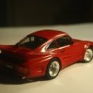
Alan R Posted July 31, 2015 Share Posted July 31, 2015 (edited) Hi All, Having just completed a REALLY, REALLY stalled build of the Beemer, I though that it was time to resurrect another Revell kit from the shelf of doom. This one has also been around the block a few times. I must have bought it a very long time ago, it's priced £4.50, and I bought it from the Lewis's department store here in Bristol.Must have been about 1978 or so... I had started this one some time in the past, but it got forgotten somewhere along the line. (That's my eternal story: Started well, never finished... ) So, on with the pictures: The box top (This'll give you an idea of how old it is...): "Molded in color.", "Real Rubber tires" etc. The obligatory sprue shots: The largely painted body and underpan: By the way, the body colour is Halfords Broome Yellow, which is a Fiat colour. Wheels and tyres: The tyres don't look too bad actually. They were a bit 'feathered' on the edges. A quick rub with a file sorted that out. The rather dinky little 3-litre V-8: Notice that I have installed ignition leads. It seemed a little bare without them. Simple to do: a very fine drill bit and some CA glue. However, where do they go to. There is no obvious distributor to plug them into... . So after a little trawling of the web, I got some images of the engine bay, and it seems that some 308s had one distributor running off the cam of the front bank of cylinders, while others had a distributor per bank, each running off the 'outside' camshaft. So, in the spirit of "doing it my way...", I'm going to fabricate two distributors, one for each bank of cylinders. That'll tidy up the ignition leads. The suspension and drive train are rather simplified. For example, there are no drive shafts from the differential, you poke a steel rod through the hole in the diff, and push-fit the wheels on to that. I'm going to ditch that (Assume that I haven't lost the steel shaft anyway ) and fabricate new shafts with "rubber" boots something like the real thing. It should look a lot better, and I don't care if you can't see it when it's all done. I'll know that it's there ... Thanks for looking, Alan. Edited August 18, 2015 by Alan R 6 Link to comment Share on other sites More sharing options...
Spookytooth Posted July 31, 2015 Share Posted July 31, 2015 Looking good so far Alan, and you have got some great ideas with the build. I hope all goes smoothly for you. Simon. Link to comment Share on other sites More sharing options...
MikeGTC Posted August 1, 2015 Share Posted August 1, 2015 Nice kit! The 308 I had from Revell was not this detailed... Mike Link to comment Share on other sites More sharing options...
Hamden Posted August 1, 2015 Share Posted August 1, 2015 Another interesting project, I'll follow along to! Roger Link to comment Share on other sites More sharing options...
Alan R Posted August 2, 2015 Author Share Posted August 2, 2015 Another update. Further to my idea of fabricating the distributors, I have started on this. here are the initial images. (Sorry for the blurry bits...) This is the initial stage, so far. The 'rounded' triangular part sits on the end of the camshafts as far as I can tell... I have drilled small holes in the camshaft covers to accept a locating pin. I am pleasantly surprised at the detail on this old kit. The copyright date on the instructions is 1979. More pictures to come.. Cheers, Alan. 2 Link to comment Share on other sites More sharing options...
Alan R Posted August 18, 2015 Author Share Posted August 18, 2015 A bit more progress. I decided that the area behind the wheels was a bit bare. I guess to keep the cost down, Revell decided not to add brakes. So, emboldened by my endeavours with the BMW, I thought that I would have another go on this one. Since I had absolutely nothing to start with, I have had to fabricate the discs AND the hubs. This is where I have got to so far: The 'kit' consists of four discs made from 40 thou card at approximately 12mm diameter. 12 discs of 30 thou card for the hub 8mm in diameter, and four discs of 20 thou card of the same diameter for the 'backing plate'. Notice that they all have a very big hole in the middle... This allows the assembly, once glued together to slip over the rather thick 'axle' on the wheel. I think that things will become more obvious when I have assembled the discs, and can show them on the wheels. I shall be using the same technique that I used to make the callipers for the BMW. I have some pictures of the 308 suspension and brakes from which I can fabricate them. More to come when the discs are made up. Cheers, Alan. 1 Link to comment Share on other sites More sharing options...
Alan R Posted August 5, 2016 Author Share Posted August 5, 2016 (edited) Finally after nearly a year! I can't beleive that I haven't touched this thing (or any other of my models for that matter...) for nearly 12 months... Anyway, enouh rambling, I have made some "improvements" to this kit: If you remember the chassis was a bit 'clunky' as in there was a lot of 'filled in' bits at the rear, like this: I decided that the chassis would look much better with them bits removed, thus: Basically, I drilled around the areas to be removed with a small drill in my pin-vice, then VERY carefully using a Stanley Knife, I cut through the holes. Once the waste plastic was removed, I then filed and sanded the rough edges smooth, giving the above result. Of course, after all that drastic surgery, I needed to repaint the floor-pan. Hence the grey bits. I also didn't like the steering 'rack', which was some kind of 'ratchet' mechanism so that the wheels would stay put. This is probably some kind of 'play' thing, I don't know. Anyway, I improved that as well. I removed the pin on the chassis that acted as the ratchet, and fabricated a new rack, thus: Not perfect, but much better than the 'toy' thing that Revell expected me to use. This fits neatly on the king-pins of the front suspension. I know, I checked.... I have also messed around with the drive-shaft and have come up with this: It's a bit long at the moment as I'm not sure how much to trim off until I fit the rear suspension. I have since re-sprayed the chassis, and have assembled the seats: the seats have also been painted a rather fetching shade of black, but are a bit 'matt'. They need to be made a bit more satin... That's all for the moment, more later, I hope... All the best, Alan. Edited August 5, 2016 by Alan R 3 Link to comment Share on other sites More sharing options...
MetroRacing Posted August 5, 2016 Share Posted August 5, 2016 Hmm I may have to seek out this kit. The Revell 308 I have is a curbside affair that looks suspiciously small next to other cars lol. Looking good, keep up the good work. Ashley Link to comment Share on other sites More sharing options...
Alan R Posted April 2, 2017 Author Share Posted April 2, 2017 (edited) Evening All, I cannot believe that I haven't reported anything on this for eight months. Well, here is another update. I have finally assembled the chassis and the cockpit. This is where we are now. The Cockpit: Dash-board added! The pedals all but disappear, but I know they are there... The kit comes with brake and clutch pedals, but nowhere in the instructions does it tell you what to do. However, it's fairly obvious where it goes as there is a slot for them in the bulkhead. No throttle pedal was provided, so a strip of 10 thou card was cut out and cemented in in the appropriate place for a throttle pedal... The gear-stick in the kit was a pretty anaemic affair, so I got a sewing pin from the wife's sewing basket, cut off the sharp bit and painted the head black. A bit of CA carefully applied with a cocktail stick, into the hole provided and it looks quite realistic. The brakes in place. You'll notice that they are a bit out on the tracking! I had made the steering rack a bit too long by about 4mm. I solved that by cutting out the 4mm section in-situ, then slipped a 1/8th" diameter tube over the two halves of the rack, then carefully aligned the two hubs so that they were parallel. I then dropped some contacta glue into the tube to set the rack to that length, followed by a bit of CA glue over the ends to strengthen the bond. This is the end result: A slightly closer look. Well, some tidying up around the wish-bones etc., and I can move on to putting the cock-pit on the floor pan, then the body shell on. Maybe it'll take less than eight months for that. Thanks for looking, Alan. Edited April 2, 2017 by Alan R Link to comment Share on other sites More sharing options...
Alan R Posted April 22, 2017 Author Share Posted April 22, 2017 (edited) Hello All, I have made further progress, mainly around the engine department and luggage compartment. Mind you, you won't be able to see any of the luggage compartment as I glued up the bonnet (hood?). Still, I know it's there... So, this is where I have got. This is the spare wheel, The rear engine deck and the louvres for the engine cover. These have been primed and painted in abbodon black. The louvres are the most disappointing part of the kit. They aren't proper louvres so that if you looked carefully, you should be able to see the engine. They are just solid lumps. Still, after fitting them to engine cover, which they fitted really well, by the way, they didn't look too bad. Here are all the bits, ready to attach together. I have also blacked in the window frames. I'm not sure if they would have been black on a car of this vintage, but I saw some pictures on 'tinternet which showed them as black. You can't see it here, but I have also blacked in the 'clam-shell' divide around the waist of the body. This angle shows the waist strip better. The engine cover wasn't too good a fit in the body. leaving it a bit proud of the back of the car. It showed as a large gap at the rear between the back of the body and the engine cover. After a bit of investigation, I saw that the sides of the engine cover were binding on the read buttresses of the body, thus: (Where the red ellipse is). So, I shaved of a tiny amount off the cover at the offending place, thus: I re-primed the shaved section, and covered the now grey bit with Tamiya X-8. The yellow was a close enough match to the body colour. This is the body after 'blacking' the window frames and clam-shell line: You can see here that the engine cover fits quite well. Well, good enough for me anyway. You can see the engine cover shuts reasonably now, The gap ther won't show (I hope!) when the body is attached to the floor. The floor. You can see the fabricated disc brakes here as well. Onwards and upwards. Glazing next. Thanks for looking, Alan. Edited April 23, 2017 by Alan R Link to comment Share on other sites More sharing options...
Alan R Posted April 22, 2017 Author Share Posted April 22, 2017 Hello again... I know that I have just posted an update only a few minutes back, but the actual work was done two days ago, the glazing was only done last night. So, two stages in the build... I got the glazing in last night. The engine cover is held in by the rear window, which after removing a fair amount of flash, and clearing up the rather prominent sprue gates, fitted with no fuss. Then I fitted the main glazing into the body-shell: Note that at this point I discovered a small problem. The glazing is supposed to fit over a couple of small pins in the roof, thus: See the two small red circles. However, due to the placement of the ejector pin marks, one of the holes in the glazing just wasn't there. So, out with a small drill in my pin-vice and hey-presto, a hole in the right place. I used the zero paints crystal clear PVA glue to keep it in place. Much safer than CA glue or poly-solvent... It fitted well. So, here are some other images: Now, I need to paint the roof-lining. I think, pale grey rather than black... Thanks for looking. Cheers, Alan. Link to comment Share on other sites More sharing options...
Alan R Posted April 22, 2017 Author Share Posted April 22, 2017 (edited) Just a small update. When I decided that I wanted ignition leads on the engine, I first realised that there was nowhere, no distributor for leads to go to, so I first fabricated the distributors for the leads to go in. OK, having done that, I then thought, there should be a coil so that the distributors didn't look a bit false. So, I fabricated a pair of ignition coils (No pictures of them on their own...). These were made out of some styrene tube with a 30 thou rod through the centre. Then I pushed over the end of the 30 thou rod a piece of insulation of one of the wires of a USB cable. This meant that I had a receptacle for where the lead could go. I then attached the coils to the rear firewall and then pushed the ends of the leads into the cable insulation. That's a lot of words where a simple picture will make more sense, so: It's not the sharpest image, but due to the lack of light and the fact that I couldn't be bothered to get out my tripod, the shutter speed was about 1/12 of a second. That means shake if hand held... Anyway, you can see the two coils attached to the firewall, and the HT leads coming from them to the distributors. I know that is not absolutely accurate. I'm not even sure where the coil (or coils) would be placed, but the firewall looked like a likely place. Anyway, that's where I have put them and it does busy up the engine compartment a little. Still quite a way to go before completion. Thanks for looking, Alan. Edited April 22, 2017 by Alan R Link to comment Share on other sites More sharing options...
Hamden Posted April 23, 2017 Share Posted April 23, 2017 That's great progress, nice to see this one coming together. Looking forward to seeing this completed it's a stunning looking car! Roger 1 Link to comment Share on other sites More sharing options...
Alan R Posted April 23, 2017 Author Share Posted April 23, 2017 Hi Roger, Than you for your kind and encouraging comments. I must admit that when I restarted this kit back in 2015, I didn't think that it would take quite this long! Still, I think that the end is in sight for this one. These old Revell kits were actually very good. I remember the Douglas 'stiletto' aircraft kit that I built way back in the 60's. That was an easy to build kit even for a 10 year old, and if I recall, the fit was good. All the best, Alan. 1 Link to comment Share on other sites More sharing options...
Alan R Posted April 23, 2017 Author Share Posted April 23, 2017 More progress, but not without some heartache! I have the interior coloured. I chose a pale grey, rather than the usual black, thus: I have also painted bits I thought would be visible but not interior black. The next attempt was to put the body onto the floor. This is where the heartache happened. The fit of the body was somewhat tight over the wheel-arches. and after some grappling, the body popped onto the floor-pan. It didn't look too bad. BUT the bonnet that I had glued in popped open, breaking the cemented join. "Not a problem!" says I, "a bit of cement should put things right!". I put some liquid cement (Revell Contacta) into the groove and thought nothing more. I decided that I would clamp it, so I man-handled the model to get the clamp in place only to notice cement all over my lovely yellow paint! Grr!!! Well, after removing as much as I could, the damage was bad but repairable. I carefully sanded the offending area and applied very thin coats of Taniya X8. The yellows, as I mentioned before are very close. I'll need to buff the area when the paint has cured, but I think that it won't be too noticeable. It won't win any awards, but I am not ashamned to put it on display and NOT into the rubbish bin of doom! Anyway, enough waffle, piccies: Sorry that the last four pictures are a bit 'noisy', but the light level was very low in the conservatory, and to get a depth of field, I was using a very small aperture on my 28-80 zoom lens. However, the rescue seems to be working. Next, wheels, lights and fenders, followed by the few decals worth putting on and she's done! Thanks for looking, Alan. 1 Link to comment Share on other sites More sharing options...
Alan R Posted April 27, 2017 Author Share Posted April 27, 2017 Hello All, This is the final assembly stage. On with the lights etc. The lights are a mix of clear parts and 'chromed' parts. Not ideal, but after the battles I have had with this in the last few weeks, trying to fabricate lenses from clear styrene was probably a bit too far! So, pictures: The wipers were left 'chrome' because the originals were chrome, I think. However, I did paint the rubbers black. It's not that obvious here. Also, if you look very carefully, there is a radio aerial at the back. It happens to exactly line up with the join in the door frame behind it! The disc brakes and callipers are visible here too. I think that they don't look too bad... The front. Looks like it's a bit skew. I blame it on stormy seas... The wipers look a bit odd, but I think it's the angle at which they are seen. The aerial is a bit more obvious here. The 'chromed' monstrosity was replaced by a bit of 30 thou rod with the end sanded to a blunt point, then painted silver. I think it looks better. Next, final assembly. Putting the wheels on. 2 Link to comment Share on other sites More sharing options...
Alan R Posted April 28, 2017 Author Share Posted April 28, 2017 Hello All, This is the final assembly. All the car needed to look like a runner was the wheels. My biggest concern was that since I had added disc brakes to the Revell hubs, the wheels would no longer fit, or would look odd or something. I was fairly sure that I had measured everything correctly and that the wheel axles would fit in the brake hubs, but you never know. After my frustrating experience with the Fujimi FIAT 500 wheels and brakes (and that was as supplied in the kit!), I was a bit concerned that my 'bodges' might have messed things up... I needn't have worried, they fitted like a dream... Not only did they fit, but the car sat four-square as well. A real bonus. The only thing I'm a bit miffed about is the fit of the bonnet. You can see that it protrudes on the right hand side. I think that it was the result of my having to re-glue the bonnet after attaching the body to the floor-pan. Nothing I can do about it now, so it will have to stay 'protruded'! I think that it also sits a little high, but I think that is a problem with the original kit and not my mods. From the front. I'm not sure about those signal lights. I might try to put them in again... When it came to final assembly, I noticed that the exhaust tail-pipe was missing from the 'chrome' sprue... So, I fabricated a new tail-pipe from a short length of 1/8th styrene tube. What would we do without 'evergreen' styrene rod, tube and sheet? I then hollowed out one end to make it look more accurate, and painted it aluminium, and the inside of it black. Beats model 'chrome' any time! Looks the part, I think. Thanks for looking, Alan. 1 Link to comment Share on other sites More sharing options...
Vince1159 Posted April 28, 2017 Share Posted April 28, 2017 She's a beauty,lovely job .... Link to comment Share on other sites More sharing options...
Alan R Posted April 28, 2017 Author Share Posted April 28, 2017 Hi Vince, Thank you for your kind comments. Apart from the bonnet 'problem', I am really pleased with the way this came out. Cheers, Alan. Link to comment Share on other sites More sharing options...
Hamden Posted April 28, 2017 Share Posted April 28, 2017 Stunning result looks great - like it a lot! Roger 1 Link to comment Share on other sites More sharing options...
Alan R Posted April 28, 2017 Author Share Posted April 28, 2017 Hello All, Roger, your kind comments are really appreciated. Anyway, I think this may be the last 'build' update for this before it goes to 'RFI'... I was really not happy about the way those front lights looked. One seemed to fit OK, but the other just looked 'odd'. When I assembled that bit, I actually put them in the wrong way round (Well, upside-down to be precise!) I am much happier. In a previous post, I alluded to the ignition coil being put on the fire-wall, but that once assembled, they would probably disappear.. Well, I looked more closely while I was doing the 'light' surgery, and you can actually see them. Whether this is accurate, I don't really care. The leads have somewhere to go, AND you can see where... There they are just in front of the engine... Well, that's put that to bed. Thanks for looking 1 Link to comment Share on other sites More sharing options...

Recommended Posts
Create an account or sign in to comment
You need to be a member in order to leave a comment
Create an account
Sign up for a new account in our community. It's easy!
Register a new accountSign in
Already have an account? Sign in here.
Sign In Now