uilleann Posted January 28, 2015 Author Share Posted January 28, 2015 (edited) OK, so a touch of progress on the nose gear leg. Attached the new tension springs permanently to the drag brace actuator arm. Laid down the initial decals for the cable attachment bands (still have the metal to do), and added a few more placards. Also got some bare metal foil on the oleo. Not perfect - but looks ok enough, I think I can live with it. If I decide I can't, I'll pull it, and try something else down the road. Also worked out a completely new landing light. The Trumpeter version was nothing short of an embarrassment. Strange too, as they look to have gotten the rear two lights on the mains more or less correct. Again, I realize I'm not even close to perfect here, but it is a lot closer to the real thing than the monstrosity included with the kit. An MV Production lens was the base of everything, then a stack of various styrene strip and square rods finished the body. Cables and the rest of the hydraulic lines to be added to the leg as well of course. Edited February 22, 2017 by uilleann 5 Link to comment Share on other sites More sharing options...
Caerbannog Posted January 28, 2015 Share Posted January 28, 2015 Impressive work - very cool. Rene 1 Link to comment Share on other sites More sharing options...
uilleann Posted January 28, 2015 Author Share Posted January 28, 2015 Thanks- I'm admittedly on the fence with the BMF on the oleo. I may try to find a different sheen than the bright chrome...or perhaps go whole hog and cut everything apart and add an actual aluminum tube instead. The look is close...but I think it maybe could be a little bit better. We'll see how much it bugs me. In truth, all three of the oleo are a bit on the short side - probably by 20-25% or so. With that in mind, the complete replacement may be the best option regardless. *shrug* Link to comment Share on other sites More sharing options...
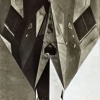
uilleann Posted February 5, 2015 Author Share Posted February 5, 2015 (edited) Alright, so I found some proper aluminum tubing for the nose gear oleo replacement surgery, and am trying to work out how best to proceed. Having never done this before, my biggest concern is of course undermining the structural integrity of what is going to be a somewhat heavy model. As mentioned above, I'm happy with neither the look of the bare metal foil I've applied to the oleo currently - nor with the actual size of the oleo itself. The image below (along with any others one finds of this A/C's nose gear) helps to show that the kit part is molded too compressed. These small metallic flashes are a definite visual focal point, so exposing a little more 'skin' here should look much more appealing and prototypical: My initial plan is laid out below: Hoping the above makes sense of course - if any of you other far more talented and brave souls have attempted anything similar in the past, can you advise on if this is viable or no? I can't really drill down into the lower section as it thins too much to be able to hide the aluminum tube. This is where I thought saving much of the original 'nub' of the kit oleo, and just thinning it's circumference to fit inside of the metal tube would likely be a wise move. As far as drilling into the upper portion, I am again afraid to take things too far in that direction either. But I would hope that 4mm is deep enough to offer a secure anchoring point. What does the rest of the room think? I have yet to cut into anything, so if I'm headed off a cliff, I hope I'll be warned off beforehand! Edited February 22, 2017 by uilleann 1 Link to comment Share on other sites More sharing options...
wanthony Posted February 5, 2015 Share Posted February 5, 2015 I can't imagine it being a good idea...if you extend the oleo the aircraft's nose will go up, you'd have to drill into the gear bay or trim the strut itself. But worst of all is the structural integrity, imagine the aircraft gets even a light push from one side or another, a strut modified in such a way at that scale isn't going to hold up, the plastic walls after drilling would just be too thin. Moreover, the point of attachment of the strut to the wheel is off to the side (as opposed to down the middle), so there will be a consistent side force on the joint. From all the struts I've seen out there, your bare metal foiled is definitely the most realistic one. I'd suggest going with what you have, and spare the headache of having to buy a new strut. But that being said, if you do feel so inclined as to try it, practice on some spare sprue first (I'd imagine that's about the same thickness of the strut). Maybe you could just get it to work... As a side note, you're doing an amazing job on the build. Keep it up! Link to comment Share on other sites More sharing options...
uilleann Posted February 5, 2015 Author Share Posted February 5, 2015 (edited) Thanks for the encouragement! To be clear, the extension needs to be completed on all three struts so there isn't a need to adjust for a high nose. In addition, this model is likely not going to be moved much (if at all really) once it's completed, so I haven't been over concerned with excessive lateral force on the gear. I was more concerned with the overall weight of the kit. As I've left the entirety of the bomb bay off this build, that will save a considerable amount of weight overall. Hoping to use that savings to my advantage. I have also given thought to inserting some smaller diameter tubing (think telescoping) inside the first, and see if I can reasonably extend that a bit further up into the top portion of the strut. That would give me more than the initial 4mm or so of contact area there. I'm making a *slightly* educated guess that the tubing is going to be stiff enough given it's relatively short exposed length, and that it would be more or less completely supported internally as well. Do you reckon I'm not thinking the engineering through proper here? And - THANKS for the insight so far. Brian~ Edited May 5, 2015 by uilleann Link to comment Share on other sites More sharing options...
Pete in Lincs Posted February 5, 2015 Share Posted February 5, 2015 From what I've seen of the a/c taxying the gear is fairly soft and bobs up & down somewhat, so extensions do vary. I like your tube idea and have done similar myself. For added strength, drill a very small hole up into the leg & insert a sewing needle. Then you can do the tube thing without too much worry. Or, can you build a hybrid metal/plastic leg using the kit parts? White metal polished up nicely. Awesome modelling so far BTW. 1 Link to comment Share on other sites More sharing options...
wanthony Posted February 5, 2015 Share Posted February 5, 2015 Oh ok, I see what you mean. You could also use the telescoping as a central support. For example, let's say you use a needle inserted into both ends of the strut, then the oleo could be a piece of alluminum tube, with a hole drilled through the middle and inserted onto the needle. But naturally, you'd need to be quite precise with your drilling and have some solid drill bits on hand. As Pete said, the oleo compresses depending on the weight of the aircraft. For example if you were to see the plane inflight, it would be extended to its max. Think of it like a spring. So unless you're trying to model a specific weight of the plane or inflight with gear entended, its length shouldn't be something to lose sleep over. One final thought to kill your buzz...if you change the length of the oleo, you'll have to redo the scissors. If they're not PE, good luck. 1 Link to comment Share on other sites More sharing options...
uilleann Posted February 6, 2015 Author Share Posted February 6, 2015 (edited) From what I've seen of the a/c taxying the gear is fairly soft and bobs up & down somewhat, so extensions do vary. I like your tube idea and have done similar myself. For added strength, drill a very small hole up into the leg & insert a sewing needle. Then you can do the tube thing without too much worry. Or, can you build a hybrid metal/plastic leg using the kit parts? White metal polished up nicely. Awesome modelling so far BTW. I had the original white metal legs for this kit - but sent them on to help complete another build of a vintage Testor's F-117A. I liked having the softer plastic available to cut into and improve upon for this build anyway. I'm just hoping to try and think through as many possibilities of what might go wrong with the tube fix here, and plan accordingly to try and avoid potential headaches down the way. Oh ok, I see what you mean. You could also use the telescoping as a central support. For example, let's say you use a needle inserted into both ends of the strut, then the oleo could be a piece of aluminum tube, with a hole drilled through the middle and inserted onto the needle. But naturally, you'd need to be quite precise with your drilling and have some solid drill bits on hand. As Pete said, the oleo compresses depending on the weight of the aircraft. For example if you were to see the plane inflight, it would be extended to its max. Think of it like a spring. So unless you're trying to model a specific weight of the plane or inflight with gear extended, its length shouldn't be something to lose sleep over. One final thought to kill your buzz...if you change the length of the oleo, you'll have to redo the scissors. If they're not PE, good luck. The more I'm thinking about things, the more I'm leaning towards the telescoping option. I can use a length of thin steel rod (no needles to hand at home) and insert that down through the bottom section easily enough as well. A visit to the local model shop is in order for more bits, but drilling everything out shouldn't prove overly difficult I hope. As for the 'proper' length of the oleos on the weighted aircraft, I've done a good fair bit of research here. I don't think I need to take any drastic measures here, but I do want to add 20-25% to all three struts to match the appearance of a loaded aircraft properly. I understand well the appearance of fully unloaded struts - and this think looks like a stork on landing and after takeoff. But for the on-the-ground appearance, the kits legs are all noticeably short. As for the scissors, the nose is PE, and the mains are two parts anyway, so my bacon is saved there. Edited May 5, 2015 by uilleann Link to comment Share on other sites More sharing options...
uilleann Posted February 9, 2015 Author Share Posted February 9, 2015 (edited) Progress...albeit slow. With the aluminum tube here, along with some brass and solid rod, I decided to get to work rectifying the appearance of the nose gear oleo. Remember, the kit part is too compressed, and then I went and added a very ham fisted application of bare metal foil. Needless to say, the result wasn't convincing: Nothing for it but more surgery and a proper metal replacement. The first cut to separate the kit oleo...after removing the PE scissors first of course: Then to finish the job on the bottom end: You can see how short the original bit was. Then to drill out the plastic to accept the new brass rod core of the improved oleo assembly: And opening it up to the final dimension: From here, it was just a matter of building up the proper parts. A 3.8 mm outer aluminum tube forms the outer 'skin' of it all. A 3.1 mm nests inside that, and then a 2.3 mm solid brass rod forms the core: Everything 'telescopes' together nicely to form a virtually solid replacement part: The shorter end fits tightly into the bottom section, while the upper longer length fits very securely into the entire top half of the kit's plastic gear leg: Everything pushed home: Looking much more the part I feel, both in terms of finish and size: Still need to tidy up the fit and finish on the legs of course, but that's simple enough. Getting closer to the 1:1 version with each step: Edited February 22, 2017 by uilleann 4 Link to comment Share on other sites More sharing options...
POTKC Posted February 9, 2015 Share Posted February 9, 2015 There us some incredible detailing going on in this thread! 1 Link to comment Share on other sites More sharing options...
xffw45343tg Posted February 9, 2015 Share Posted February 9, 2015 Looks fantastic! I had feared that the aluminium might look too, well, "aluminiumy" but it does a remarkably good impression of steel. And of course, there's the added advantage that you can now put in a little steering angle if you so choose. My brother-in-law works for one of the companies that make/refurbish the real units. I'll try and remember to ask him what the sliding member is made of/coated with. Kirk 1 Link to comment Share on other sites More sharing options...
Pete in Lincs Posted February 9, 2015 Share Posted February 9, 2015 Looks much better. I'm glad it worked out for you. The shiny part is known as the fescalised portion. (Well it's pronounced as that. The spell check doesn't like it!) 1 Link to comment Share on other sites More sharing options...
mixup_1 Posted February 9, 2015 Share Posted February 9, 2015 UNREAL Detail!! Breath taking!! Love it!! Thank u soo much for sharing!! 1 Link to comment Share on other sites More sharing options...
uilleann Posted February 9, 2015 Author Share Posted February 9, 2015 Thanks all. The shine on the aluminum looks very close to steel with my mark 1 eyeball - though I know the macro lens does no favors for our kits! I spent a deal of time polishing the surface and finished with a couple coats of polymer paint sealer for the car. Hoping the shine lasts. The feel of the leg gives an impression that it's overall strength has been increased somewhat as well. And I do like the possibility of adding a slight turn to the nose wheel. One more little detail to add a touch of added realism to the finished product perhaps. Cheers! Link to comment Share on other sites More sharing options...
prowler0000 Posted February 9, 2015 Share Posted February 9, 2015 Just read your build from the start, & liked every update you've posted. Although no longer an aircraft modeler, I am still appreciative of a quality build, & this certainly qualifies as such. I must admit to being slightly disappointed when you went for the resin 'pit, but fully understand the reasoning behind your decision..... Silly question, but is she gonna be "regulation" overall black, Black with the stars 'n; bars underside, or the funky camo paint-job? 1 Link to comment Share on other sites More sharing options...
uilleann Posted February 10, 2015 Author Share Posted February 10, 2015 Thanks! To be honest, I was very hesitant on the Aires cockpit myself at first. But after taking a chance and dropping more than a few hard earned pennies towards it - I couldn't be happier. It addresses just about every niggle I had with the Trumpy version of the same, and the quality of the casting is absolutely first rate. After a splash of paint, and a few cables here and there for added visual candy, the look is unbeatable. Did you see those MFD screens? My only quibble really (and it was a small one) was having to hack into the sills to fit the resin, and consequently needing to redrill the canopy latch holes. As it stands now, I have an unused Trumpy F-117A cockpit sitting here collecting dust. I can always throw it in the post to you if you feel a need to salvage it. I know my skill level isn't anywhere near many of the masters here, but I don't feel too terrible after so much time off, and really only have plans to do this kit and be more or less done. No stash. No permanent bench. And everything just picked up as I've gone along here with this build. I was inspired years ago by a build of this same aircraft I saw at an airshow (must have been the old 1st generation Testors kit with all it's horrific shape issues, but I didn't know it at the time), and the maker had gone all out detailing it. I saw the jet at the same show in the flesh, and it left a lasting impression. As for the finish, I am planning on the common black. But I have a few ideas knocking about that I hope will help it turn out a bit uncommon. We'll see if my fingers can reproduce what my brain is thinking. I'm surprised that so many often tend to think of black aircraft as only that. When the reality seems more often than not - particularly at scale - to be numerous greys, browns, reds, blues and a myriad of other subtle shades. The most realistic 'black' finishes I've seen are often anything but black. I also think it takes more than panel lines and a splash of weathering here or there. With any luck, I hope to be able to pull it all off well enough! In the mean time, I'm going to work on finishing up the gear as they're one of the focal points of the otherwise dark aircraft. I'm hopeful that some of the attention to detail here will really pay off in the overall look and feel of this kit when completed. My ideal scenario would be to create a small diarama and case for it, and donate it to the local Air Force museum to display in one of their halls. We'll see if it ever gets that far. 3 Link to comment Share on other sites More sharing options...
wanthony Posted February 10, 2015 Share Posted February 10, 2015 That gear leg is definitely a lot bigger than I perceived....but hats off to you, what you've done looks quite amazing! 1 Link to comment Share on other sites More sharing options...
uilleann Posted February 10, 2015 Author Share Posted February 10, 2015 It's 1/32. Or at least as close as Trumpeter makes that to be here. Is that what you're referring to? Link to comment Share on other sites More sharing options...
wanthony Posted February 10, 2015 Share Posted February 10, 2015 I've never built 1/32, and I didn't get an idea of the scale until you took a picture of the strut next to the pin vise! 1 Link to comment Share on other sites More sharing options...
spruecutter96 Posted February 10, 2015 Share Posted February 10, 2015 PM sent, re: offer of the kit cockpit. Many thanks. Chris. 1 Link to comment Share on other sites More sharing options...
uilleann Posted February 10, 2015 Author Share Posted February 10, 2015 I've never built 1/32, and I didn't get an idea of the scale until you took a picture of the strut next to the pin vise! I've been stuck staring at the gear for so long, I've managed to leave the main fuselage boxed up till it's ready for final assembly, and forgotten how large the kit is overall. It certainly beats the Tamiya 1/48 for size (of course). I must say I really like the 1/32 scale for scratch building, as it is large enough to be both more manageable than 1/48 for me, and also more visible in the finished kit when all is done. The nose gear with wheel in place and all measures approx 75mm top to bottom, to give some sense of scale. PM sent, re: offer of the kit cockpit. Many thanks. Chris. Hi Chris, Received and replied. Cheers Brian~ Link to comment Share on other sites More sharing options...
James G Posted February 10, 2015 Share Posted February 10, 2015 Great work & a very enjoyable thread. 1 Link to comment Share on other sites More sharing options...
uilleann Posted February 11, 2015 Author Share Posted February 11, 2015 Cheers James - thanks for that. Link to comment Share on other sites More sharing options...
uilleann Posted March 9, 2015 Author Share Posted March 9, 2015 (edited) OK, a touch of progress. Sadly, not in the area I was hoping for. Because - SHINY! Yeah, got distracted by a couple other issues to work on in the nose gear well as I was waiting for the hex rod to arrive for the door uplocks. A few more bits and bobs in the well here. New hydraulic reservoir and small tension spring just forward of the drag brace actuator arm attachment to the roof of the well: Added some missing rivet detail to a small panel up front, missing from the kit and the Eduard update. (Needs a paint touch up in a bad way...but the bumps are there at least): And lastly, another bit of (relatively) large surgery for the nose gear itself. There is an upper hydraulic piston that the kit had molded on the direct center line of the strut. In reality, it is offset to the port side. The more I looked at the images, the more I wanted to correct this error. Particularly as it helps to make the part much more visible, and helps to busy up everything. So a few cuts with the Xacto later, and the part was free to be modified. A notch added to the rear, and a new mount made from 0.010" card. The mount was a complete guess really, as the only images I have show it only edge on. Mounted to the port edge of the upper strut, and carved to what I hope isn't an outlandish final shape. I am pleased with the final look of things with the new and improved offset: A touch of paint here and there, along with a few minor touch-ups, and I should be ready for work on the door uplocks very soon. Cheers B~ Edited February 22, 2017 by uilleann 9 Link to comment Share on other sites More sharing options...

Recommended Posts
Create an account or sign in to comment
You need to be a member in order to leave a comment
Create an account
Sign up for a new account in our community. It's easy!
Register a new accountSign in
Already have an account? Sign in here.
Sign In Now