Search the Community
Showing results for tags 'Airfix'.
-
Messerschmitt Me.410-1/U2 & U4 (A04066) 1:72 Airfix The sleekly styled, twin-engined Me.410 Hornisse started life as the Me.210, the intended replacement for the Bf.110 that was already showing its age, and forward-thinking planners correctly anticipated that if war broke out, it would quickly be outclassed, leading to heavy losses. The replacement process was begun before WWII started in the West, but turned into a protracted gestation due to problems that presented themselves before it could be turned into a viable heavy fighter/bomber. The Me.210 was a flawed concept that suffered from unpleasant and sometimes dangerous handling characteristics, garnering such a poor reputation that when the substantial changes needed to fix these problems (initially designated the 210D) were underway, the decision was made to rename it the Me.410 to distance it from its origins. The 410 utilised an improved DB603A engine, lengthened the fuselage over the 210 to improve the centre of gravity, utilising an amended wing planform to give it a constant sweep-back of the leading edge to bring the aerodynamic centre further forward. Coupled with leading-edge slats that had been removed from the initial 210 design, the resulting aircraft that was significantly more pleasant to fly, had a respectable top speed and could carry a substantial war-load. On entering service in 1943, its initial success as a night bomber over the UK was most definitely not a portent of great things to come. The 410 was a day late and a dollar short so to speak, and no sooner had it reached the front-line and started attacking the bomber streams, than the Allies darkened the skies with fast, manoeuvrable single-engined fighters such as the Spitfire and Mustang, which could easily out-fly the 410, a problem that would be exacerbated by later designs such as the P-47 Thunderbolt and the P-38 Lightning. Pitched into battle without fighter cover, they were easy prey to the Allied fighters, and the balance was only slightly shifted by the introduction of Bf.109 and Fw.190 escorts. Production ceased in August 1944 to concentrate dwindling manufacturing capacity on the Emergency Fighter Programme for the ultimately unsuccessful defence of the Reich. Due to its relatively short career, the marks that saw action progressed only as far as the B model, although high altitude C and D models were on the drawing board, but never saw service. Despite its flaws, the 410 was quite innovative in its weapons carriage, and had a nose-mounted weapons bay directly under the cockpit, which could house a palette of munitions, either bombs, cannon, reconnaissance cameras or the 50mm Bordkanone that was used to attack daylight bomber streams. Due to the upgraded engines that gave it more capacity in the bomber role, a pair of bomb shackles had to be added to the inner wing undersides to accommodate the extra load. The twin remote controlled "barbettes" on each side of the mid fuselage were also of note, as they were controlled by the rear gunner from the aft cockpit using a traditional pistol-grip system could also pivot up and down, but the barrels could also be rotated out sideways to fire one of the two barbettes at an off-centre target behind them. Movement and aiming was all carried out using controls attached to the pistol grip, and must have surprised more than one potential assailant. The A-1 model was designated as a Light Bomber, a job that it was well suited to, giving the Allies a run for their money on night operations, where they proved difficult to catch. The 410’s equipment bay right beneath the pilot in the A-1 accommodated the nose armament of a pair of MG17s and MG151/20 cannons, plus shackles for droppable munitions, with a maximum of 1,000kg. A pair of 500kg bombs was the usual, but other stores could be carried. The underside of the nose bay had two clamshell doors that partially retracted into the fuselage, allowing easy exit for the bombs. After the war, several of these interesting aircraft were taken as war prizes by the Allies, but sadly only two full airframes exist today, one in RAF Cosford in a fully-restored state, which until the 1980s was capable of ground-running despite props that were shortened to equalise their lengths after an “incident”, the other awaiting preservation in the US at the National Air & Space Museum. The Kit This new tooling from Airfix was announced only shortly before release, and caused a stir amongst 1:72 modellers, as it was an unexpected new tooling, and a slightly unusual subject matter when you consider its relatively short length of service. The kit arrives in Airfix’s red-themed top-opening box, and inside are six sprues of dark grey styrene, a separately bagged clear sprue, decal sheet inside the instruction booklet that is printed in colour on matt paper that is accompanied by a single A4 colour printed sheet of profiles for painting and decaling the model. Detail is excellent, and the part-count at 137 is commensurately high, with much work going into the cockpit, weapons bay, gear bays and the other usual focus areas, plus finely engraved panel lines and crisp clear parts that have been engineered in sections to recreate the twin bulged aft sections around the gunner’s position. Construction begins with the cockpit floor, which has the side consoles moulded-in and has decals to highlight the details. A window is inserted into the forward floor, installing the gun pack below in what will become the weapons bay. A scrap diagram shows the location of two 1mm holes that should be drilled in the floor before the next step, which is fitting the pilot’s seat and the bulkhead with head-rest behind him. The control column and a small instrument rack are fixed to the floor, then an extension to the cockpit is fitted behind on a lug, which is used to support the frame around the gunner’s position, adding extra details to the frame before joining it, and a suspension arch in the weapons bay below it. Work on the cockpit stops for a while, as the gunner’s position is built on the wing lower, which must be built next. The lower wings are moulded almost full-span, drilling out flashed-over holes depending on which decal option you have chosen. A combined spar and gear bay bulkhead part is inserted into grooves in the lower wing, strengthening the assembly further, then adding the gunner’s compartment, which is made from a tub with a separate rear that is covered with moulded-in radio gear boxes, and the seat on the top edge of the area. It mounts in the centre of the wing aft of the spar on four turrets, the forward edge of the compartment butting up against the spar, overlapping it slightly. A triangular door insert fills the gear bay opening for the gear-up option, then the bays themselves are installed, with plenty of moulded-in detail for the avid viewer to look at. The fuselage must be completed next to join the two crew compartments, in advance of finishing the wings. The starboard fuselage half has an electrical panel applied near the rear of the cockpit, and half of the pilot’s instrument panel plus decal at the front, adding a bulkhead to the front of the tail-wheel bay, painting it all interior green RLM02. The port side has just the instrument panel half installed and decal at the front, then has the cockpit glued into position, with location assisted by a scrap diagram nearby, then the fuselage halves are joined around a drum without glue, which will be the base for the rear gun barbettes. Once the glue has cured and you have dealt with the seams in your usual manner, the fuselage is lowered onto the lower wing taking care not to damage the gunner’s compartment, and is glued in place, followed immediately by the two upper wing halves. With the glue cured and seams dealt with, you have a choice of dropped or retracted leading-edge slats, using different parts for each option, and ensuring you don’t get them mixed up! The elevators are next, and again you have a choice by using different parts, offering dropped elevators without having to do any additional work, or having them neutral by replacing the lower section that has the flying surfaces moulded-in. The assemblies fit into slots in the tail with zero dihedral, and the rudder panel is inserted into the fin, which can be posed deflected as you wish. The engine nacelle fronts are made from two halves, adding the cooling bays from two parts each underneath, then sliding them into position in the wing fronts, leaving the small gear bays open to receive the struts later in the build. Another choice is armament in the weapons bay, depending on which decal option you are portraying, each one having a different set of doors for the relevant armament. Decal option A is the U2 variant that carries a pair of 20mm MG 151/20 cannons in a pod inside the bay that has 250 rounds available and fitted on a peg inside the bay, with an insert on each side that is moulded to a carrier. The U4 carries the long-barrelled 50mm Bordkanone with 22 rounds, the barrel for which is installed in the separate cowling that uses the same insert at the rear. The completed assembly of choice is then glued into place under the nose to complete its distinctive snub-nosed profile. The next choice is whether you wish to depict the radiator fairings with the cooling flaps open or closed. The radiator cores are common to both options, and the two sides are joined by a trio of turrets, then they are inserted into the radiator fairing of choice, adding the sides to the assembly appropriate to the position. The outer flap panels are inserted into gaps in the wings behind the radiators at 10° deflection for the open option, then the fairings are installed into the depressions in the underside of the wings to complete them. The ailerons are next in line outboard, and are fitted with a pair of horn balances into slots in the parts before they are installed in their bays, and these can be posed deflected if you wish. There is still much to do, starting with the exhaust stubs that are moulded on a carrier, and slotting them into the nacelles on each side, then adding flare hiders that help protect the pilot’s night vision and make the aircraft less visible at night. The barbettes on the sides of the fuselage must be glued carefully to ensure they remain mobile, adding the gun barrels into the slot at the rear of the fairing to complete them. If you are building your model on the ground, the main wheels of the 410 are supplied in well-detailed halves with a smooth tyre that has a little sag moulded-in to depict the weight of the aircraft compressing them. Each gear strut has a separate scissor link spanning the black gaiter over the oleos, adding a retraction jack behind the leg as they are inserted into the bays, gluing the wheels on the inboard side, and fitting a bay door to the front of the bays. For retracted wheels, a single part covers the tail-wheel bay, which is substituted by a pair of linked open bay doors for the wheels-down option, after which the nicely detailed tail-wheel strut with moulded-in wheel is glued into the bulkhead inside the bay. The next option is dependent upon whether you drilled out holes in the lower wing earlier, which receives two underwing tanks that are made from two halves with handed support frames suspending them under the aircraft. The three-bladed props are moulded as one part, and are trapped between the spinner and back plate, then a stepped washer is slipped over the axle at the rear without glue, and is trapped in position by another washer that is glued into position to allow the prop to remain mobile unless you overdo it. The two completed props are slotted into the fronts of the engine nacelles, and these can be left until after painting to avoid damage or messing up part of your paint job. Before the canopy can be installed, two triangular supports are added to the space between the crew positions, and the gunner’s two-part control centre with pistol-grip is fitted at the rear of his compartment. The unusual glazing strip that extends the pilot’s view over the nose is different depending on which armament option you have chosen, using different parts accordingly, then building the complex shaped canopy from three components. The windscreen has the entire canopy roof moulded-in, and it is completed by gluing the two side glazing components to the sides to achieve the correct tapering, yet bulbous shape at the rear. This is glued into position along with a radio mast offset to the starboard roof frame between the crew stations at an angle to the vertical from the front, adding a pitot probe to the port wingtip, and if the aircraft is wheels down, a crew access footstep that drops from the fuselage on the port side. Under the fuselage are fitted a long towel-rail antenna and another straight mast with a bulbous end. Markings There are two decal options on the sheet, which share the same splinter scheme on the wings, but have different patterns and mottling on the fuselage. From the box you can build one of the following: 11./Zerstörergeschwader 26, Gardermoen, Norway, 1945 Stab II./Zerstörergeschwader 26, Königsberg, 1944 Decals are by Cartograf, which is a guarantee of good registration, sharpness and colour density, with a thin gloss carrier film cut close to the printed areas. Because of the proximity and limited space between the fuselage and engine nacelles, scrap diagrams show the locations of the various markings and stencils in those locations that would be invisible on standard profiles. Conclusion This is an extremely well-detailed modern kit with an interesting choice of weapons fits and plenty of other options to personalise your model. Very highly recommended. Review sample courtesy of
-
Keeping my hand in - Lightning F6
Enzo the Magnificent posted a topic in Work in Progress - Aircraft
I now find myself in a strange situation. I have six concurrent builds, five of which are likely to be finished over the weekend. I have never had so few ongoing builds in at least ten years. Things will get back to normal after the new year when the 2024 groupbuilds swing into action but until then I need something to keep my hand in. So I thought it might be nice to build an English Electric Lightning. I haven't built one for a few years now, so it's about time. I will build the Airfix 1/72 kit. The box art is bizarre as the artist forgot to put the tailplanes on. Later issues of the box have that rectified. I'm going to build the second option, a grey jet from the Lightning Training Flight (aka 11 Sqn). I have never built a grey Lightning before. There were a number of grey schemes carried by the Lightning. This is the darkest of the schemes. So here are the sprues. Photos are taken (with permission) from the Britmodeller review. All the above sprues are in the F2A boxing. To cater for an F6, Airfix add an additional sprue. Yes, one of the fins on the Red Top missile is short shot. It's the same in my kit as well. The kit was originally issued ten years ago. The sprues in my kit are exhibiting some flash, notably around the wing trailing edges, Firestreak missiles and IFR probe. Considering that the kit has sat in The Stash for a good five years, the amount of flash from a five year old mould is puzzling. -
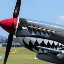
Hello all, Here is my last completed model for the year, the Airfix Hawker Tempest (A02109). I didn't use the kit decals for the main markings, instead using my Silhouette Portrait cutter for the roundels, SQN codes, serial number and walkways. I used Tamiya masking sheet but it was a bit uneven on the fuselage and under wing roundels so I might have to use vinyl like I did with the serial number next time. I also chopped off the gun barrels and replaced them with needles but apart from that it's all OOB. I used Humbrol enamel for the roundels but the rest of the kit was painted using SMS acrylic lacquers, followed by a panel wash and for the first time I used pencils for some weathering. Painted up in the colours of a 3 SQN aircraft flown by FLTLT John 'Bay' Adams RAAF in which he shot down a FW190 on 30 April 1945. Post WW2 he flew Mustangs in Korea with 77SQN, commanded 76SQN in Malta and the RAAF Contingent Vung Tau in Vietnam before retiring in 1979 as an Air Vice Marshall. Thanks for looking and a Merry New Year to everyone. JG.
-
PS Great Western (A08252V) 1:180 Airfix Vintage Classics Designed by world-renowned engineer and architect Isambard Kingdom Brunel, the PS Great Western was the inaugural vessel owned by the eponymous Great Western Steamship Company. She was designed specifically for transatlantic travel, and was for two years the largest passenger ship afloat until superseded by the SS British Queen, which allowed it to claim the crown because it was delayed getting into service, but was itself outstripped only a year later. The Great Western was an oak-framed vessel that was iron-strapped for strength, and was equipped with four masts, which were a useful back-up power source for any failure of the steam-driven paddles on the sides of her hull that were intended to be her primary motive power. She went into service in 1837, almost catching an older ship that had departed four days earlier, cementing her claim for high-speed crossings at over 8 knots and cutting down travel time to around 16 days. On arrival in the US, a shipboard fire broke out and Brunel himself was injured after falling 20ft in the commotion, the fire putting off many customers for the return journey back to England. She served as a passenger liner for some years until the company went bankrupt following the running aground of her sister ship SS Great Britain that was stranded until refloated at great expense to the company, bringing them to their knees soon after. The Great Britain was eventually sent to the Falklands where she remained until brought back to England in the 1970s, with a view to restoring her, which eventually came to pass. The Great Western was sold to another shipping company where it travelled between the West Indies and Southampton, then other routes until 1855 when she was laid up back at Southampton, where she languished until used as a troop transport during the Crimean war, where she was referred to as Transport Number 6. She was sold for scrap a year later in 1856 and was broken up at a yard on the Thames, unlike her sibling who can be seen most days in a dock in Bristol thanks to the philanthropic efforts of Sir Jack Arnold Hayward and others. As subsequent steam ships were patterned on the competent design of the Great Western for some years after she was laid down, the Great Britain is probably as close as you will get to seeing her today. The Kit This kit first hit the shelves of your local model shop in 1966, before many of us were even born, which is why it’s in the Vintage Classics range, with the implication that you may need to apply some modelling skills to bring it up to today’s standards unless you’re just building it for fun or a trip down memory lane. Detail is as you would expect for the era, and there is a very slight bit of mould damage from the intervening years and multiple re-releases that it has endured. The good news is that it’s infrequent and amounts to a few surface blemishes for the most part. The scale is an unusual one for the modern modeller, but in the 60s rigid adherence to scales wasn’t all that important, and this results in a healthy 400mm long model that would look good on anyone’s shelves. The kit arrives in a sturdy red-themed top-opening box, and inside are nine borderless sprues and three hull parts in a toffee-coloured (think Caramac) styrene, a black sprue that contains a rigging jig, a vacformed sheet of off-white styrene for the sails, and two bobbins of thread for the rigging material. The instruction booklet is printed in colour, and hidden inside is a sticker representing the red ensign, or “red duster” as it is sometimes known, printed in a manner that gives the impression of a flag rippling in the breeze. Construction begins with the hull, which is moulded in halves with a deck that locates on a raised rim inside, which has a lug above it, with a scrap diagram showing where it should be in relation to several holes in the deck. The stand is shown built next to it, moulded as a cruciform part with upstands moulded into the longer ends, and separate supports on the shorter arms. It will be useful to have the stand built early on, as ships gave rise to the phrase “keel over” because they generally don’t have flat bottoms. Seven skylights are dotted around the main deck, and two raised hatches are added to a stepped section amidships behind the funnel base, fitting a circular quarterdeck on a semi-circular step, and installing a three-part gallery around the stern with the impression of windows moulded-in. Two-part railings are fitted around the fo’c’s’le, all of these installations fitting on pins into holes in the deck, or on raised boxes. The huge paddle wheels that propel the ship through the water are made from a lamination of three large wheels, then a set of paddles are arranged at regular intervals around the circumference of both wheels, with a scrap diagram showing which way they should fit in relation to the direction of travel. There is a little flash and clean-up needed around each paddle, so set aside some time for this to avoid frustration. Before installing the wheels, the fairings around it must be put in place, fixing large stepped sections into the deck, and bulking them out with additional parts, adding a pair of supports below where each arch will fit in the next step, shrouding the upper portion of the wheels to prevent spray covering the decks and crew. Rows of covered portholes reminiscent of a galleon’s gun ports are inserted into the hull fore and aft of the paddles, fitting the figurehead under the bowsprit base with a pair of cat heads (not literally) on the cheeks of the bow, and a capstan near the bow. The funnel is moulded in halves, and is inserted into the deck at a rakish angle just forward of the paddles. The lifeboats are made from a hollow hull with separate gunwales that incorporate the bench seating, to which two pairs of oars are applied, before they are suspended from the rear deck on a pair of davits that pin into the deck. The quarterdeck has a large section of gridwork moulded-in, and the ship’s wheel is built in the centre from two handle-studded wheels trapped between pedestals, and a compass mounted in front for easy viewing by the helmsman. The rudder under the stern is added below the quarterdeck, and two sets of steps for the crew to come and go, adding a set of three-part railings around the deck so the crew don’t end up in the drink. The next step involves installing the simplified lower shroud deadeyes and adjusting ropes as dog-bone shapes that fit into holes in the deck at the base of each mast, building the masts from two lengths with overlap, adding spreaders at the half-way point, diagonally placed gaff rails to the rear of each mast, plus two cross-masts on the forward mast. The bowsprit is a single part that fits under the fore deck, and it might be wise to leave the masts loose in their sockets until you have completed painting and rigging has begun. A large double-H frame links the two paddle arches athwartship, and creates a walkway with steps up and down, as shown in a scrap diagram nearby. The next page is a rigging diagram that also shows how to mount the anchors on the bow, and how to make the ratlines that run from the lower shrouds to the spreaders where the mast poles overlap. There are various additional rigging lines that stabilise the masts fore and aft, and keeps the gaffs in position, as well as lines to the bowsprit, but what makes me really sad is that I don’t have an excuse the use the word “futtock” when describing the rigging of the Great Western. The thread that is provided on the two bobbins is a braided cord, but there are still small quantities of fibres visible in the light, and some modellers may wish to replace it with another type of thread. There is a two-part rigging jig included in the box and its function defied my understanding initially until I flicked through the booklet and found an explanation that runs over two pages in English and nine other languages. The last instruction step details the use of the vacformed sheet of sails, which are moulded on the curve as if sailing at full speed, and they should be cut from the backing carefully with a sharp knife, preferably with support behind from Blutak or modelling clay, sanding the edges smooth once they are free. The individual sails have raised details moulded-in, and a letter next to each of them that corresponds to the diagram of the ship at the bottom of the page devoted to their fitting. Secure the tops of the sails with glue to the masts, then add extra rigging lines to the bottom corners, taking note of their locations from the box art, as the formal rigging diagram doesn’t show the sails or rigging lines specific to them. There will also be tackle blocks on some of lines, which could be replicated by slices of sprue or by adding blobs of PVA or other glue to the lines once in position, and painting them when they are dried. Markings The PS Great Western is depicted as she appeared in 1837 with copper bottom (where the phrase originated) and black hull sides, decorated with gold details. Two scrap drawings show parts of the deck at an angle to assist with detail painting, and an overhead drawing completes the instructions. The red ensign is shown suspended on a length of fine cotton between the gaff on the rear mast and the stern, but it is shown fluttering forward in the main diagram, which would be unlikely. The sticker folds down the centre mirror line, trapping the cord in position, after which you can glue the line into position under slight tension. Conclusion This is an old kit, but it is wearing well and it is still the only injection-moulded styrene kit of the ship in a relatively large scale, so it’s the best option to build. Sympathetically painted, weathered, and with tidy rigging will bring admiring glances from viewers. Recommended with the usual caveats of an older tooling. Review sample courtesy of
-
Today’s lunchtime Bargain Hunt on BBC1 was a Toy Special, and I perked up when one of the teams found a trader with a stall full of Airfix kits in boxes. These were old kits, and the team decided to buy some. They chose a meteor, Kingfisher, Viggen and a lunar landing module. I didn’t get a chance to see details like scale, etc.. I saw a price ticket on the lunar module, £34.95 - whether that was the original price or the dealer’s price I couldn’t say. anyway, the team paid £80 for the four kits, which fetched £20 in the auction. whoever bought them got a tremendous bargain, essentially four kits including a lunar module notionally £35 for a fiver each!
-
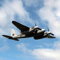
Hi all This is my entry for the informal GB with Roger @Dunny, who persuaded me to join this. So far it is just the two of us but feel free to join in with a build too. I will be using the lovely Airfix 1/72 RF.X, which I am already using in another build as an FAA Mk.II on my FAA builds thread. I have had to purchase another one fir this build (I also have TF.10 in the stash to build as a TT). The kit I won't bother with a sprue shot as Roger has added one to his thread I will be using this lovely PE set from Eduard, I have used the same set in my FAA build and it makes for a convincing cockpit. I am going to have a go at NE832 PL-Q of 144 RAAF squadron, as illustrated here , which is on part of the wonderful Aviaeology decal sheet. I hope Terry at Aviaeology doesn't mind me posting this image, it will be removed if he wishes. I could not find any images of this aircraft only a sister machine following a crash landing. I like the various shades of paint following use and overpainted Stripes etc. I also could not locate the Decal sheet as it's out of stock with Aviaeology and everywhere else I looked so I have some correct sized letters out of one of the sets in my decal collection so will use those and paint them black. I will wait for the Green light from Roger as GB coordinator 😉and will be off the blocks. Link to Roger's thread , his last image in the initial post shows NE832 in the backround. Thanks for looking Chris
-
Finish no6 of the year and probably the last one is Airfix's Hawker Tempest in 1/72, its a nice little kit that has some advantages over the earlier Typhoon but has the same fit issue around the nose area. Been slowly putting together along side the Blenhiem IV that was finished a few months ago and finally completed yesterday. Built straight out of box as an aircraft of N0486 sqn, Royal New Zealand Air Force, Castle Camp, Cambridge, Apr 1944. Painted with the usual Tamiya and Mr Hobby Colour acrylics with some oil paint washes and Florys Dark Dirt clay wash. I ended up painting the leading edge stripes as I couldn't get the decals to sit right and lost some of the smaller underside stencil data.
-
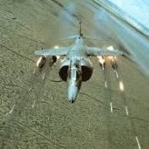
 Hi All, My next project will be Airfix' newish (2015) Beaufighter TF.X, finished as LZ407 of 455 Sqn RAAF, which was part of the Dallachy Strike Wing. Now I completed a 1:48 Banff Strike Wing Mossie last year, so this is the next stage of the project! I'm very happy to say that I'll be building alongside the Hairy Stick Wizard himself, @bigbadbadge! We thought we'd have a bit of fun with an informal group build, so anyone who cares to join the banter is more than welcome. @AliGauld has already presented a note as he built a Dallachy Beau last year, @mark.auis busy with his Air Ministry ME262, but anyone else feel free to jump on board! I've built a couple of 1:72 Airfix Beauforts and a Blenheim Mk.IV this year - I was enormously impressed with both kits so am looking forward to what this one has to offer. Here's the box art: Here's the sprues, in Airfix usual 'old' soft pale grey plastic: This is going to be largely OOB, although I have a mask set: Now thus far I have been unable to find photos of LZ407. I do have information on the scheme (Chris has kindly shared with me details of the Avieology decal pack, which I shall not publish here for copyright reasons). However, the scheme states that the airframe was originally delivered to the squadron in 1943, and was certainly sometime equipped as an RP-armed aircraft. Here's some shots of contemporary aircraft from the wing (144 Sqn) (copyright IWM - images for discussion only and will be removed on request): These were heavily weathered airframes, so this should be fun! Specifically of note: - Oversized black squadron & aircraft codes - Overpainted areas of the original 'Sky' code letters - Overpainting of both upper & lower invasion stripes - Specific patched areas of flak damage, along with a replacement tail I'll also need to pay attention to the RP layout, as I believe it was specific to the Dallachy Beaus by this time. This is a bit of a placeholder as I'm still busy with my Typhoon & Hurricane II.c at the moment, but looking forward to kicking this one off with Chris! Thanks for looking, Roger
- 69 replies
-
- 11
-

-
Fairey Gannet AS.1/AS.4 (A11007) 1:48 Airfix The Gannet was another great British aircraft that began development while the fires of WWII still burned, and was specifically designed to take advantage of new radar technologies that had been developed during wartime to perform the complete anti-submarine warfare task, taking the role of both the hunter and the killer. Early design work experimented with the use of a single turboprop engine for fuel economy to allow the aircraft a long loiter time, but this was found to be sub-standard, and Rolls-Royce cancelled the engine design to concentrate on more pressing wartime needs. The Armstrong Siddeley Mamba engine was considered as an alternative, and it was decided that two of these engines with a common intake and gearbox would be suitable. Known as the Double or Twin Mamba, that gave the design a wide ‘chin’ and twin exhausts. The engine would power two contra-rotating props that had dual roles, eliminating any torque steer effect on take-off and landing, and giving the crew the option of shutting one engine down to save fuel and extend loiter, as there was enough power in a single engine to keep the aircraft aloft. By 1946 Fairey had been given a contract to produce two prototypes, which first flew toward the end of 1949, and the testing programme ironed out the bugs, which included a crash-landing that damaged one of the prototypes and caused some delays. By 1950 the testing process had progressed to the carrier trials portion, carrying out the world’s first carrier deck landing by a turboprop aircraft. The second prototype was completed later, and had benefited from changes to the design based upon experience with the first airframe, which had now racked up two crash-landings. Other changes to the specification were forced upon them too, including a larger bomb bay, an additional crew seat and canopy, and relocation of the radome, all of which was mirrored on the first prototype to ensure its ongoing usefulness to the testing programme. Successful completion and the increasing likelihood of war in Korea led to an order of 100 AS.1 airframes, reaching service by 1954 after resolving a compressor stall issue that had grounded the first production batch for two months. The AS.4 was created later in the 50s, with better engines and avionics, then to replace the ageing Skyraiders in the AEW role, a fundamental re-design of the fuselage was made to accommodate the large radome centrally mounted under the wings, which was designated AEW.3, and was fitted with a new variant of the Double Mamba, which can be easily differentiated from the earlier marks by the fuselage design and the heavyweight radome underneath. Export customers included Germany, Indonesia, and Australia, where they stayed in service for a long time. In the 1960s the Royal Navy transitioned the ASW role to helicopters, effectively making a proportion of the Gannet fleet redundant, but they were found alternative employment with a few alterations, some performing the Electronic Warfare role, and others converted to mail delivery and communications aircraft, travelling between the carriers and shore establishments. By the late 70s, the British Government had mandated a retirement of the Navy’s last carriers, which it was assured were unnecessary, and the Gannets were retired at around the same time, leaving the fleet with a capability gap just in time to make protecting the “through-deck cruisers” and the rest of the Task Force ships during the Falklands War. The Kit 1:48 modellers have never been well-served with Gannet models, although for years the best choice was the Dynavector vacformed kit, with the Classic Airframes coming second, despite being at least partly injection moulded. Both required more modelling skill than your average injection-moulded kit, and both are long extinct, although I still have one of the Dynavector kits on my shelf as I type this. A few months ago Airfix announced they would be releasing a brand-new tooling of this classic post-war British work horse, which caused a great deal of happiness amongst British and anglophile modellers, promising a modern injection-moulded kit that wouldn’t take arcane incantations or selling one’s soul to a deity of your choice to successfully complete. It has now arrived, and the wait has been worth it. The kit arrives in a large top-opening box that is filled with seven sprues in Airfix’s recent dark grey styrene, plus a single sprue of clear parts, finishing off with a large decal sheet and the instruction booklet, which is printed in colour and has two separate A4 sheets of glossy paper depicting the markings options and stencil locations. If you have seen the newly tooled 1:48 Buccaneer or Sea King, you will know exactly what to expect, which is a ton of detail, clever engineering, and multiple options that give you flexibility of completion of your model without the results looking toy-like. The surface detail is excellent, covering the skin with engraved panel lines and fine rivets, plus deeply recessed detail in the bomb bay, cockpit and landing gear areas, which are the focal points of any aircraft model that carries a pilot. The front page of the instruction booklet carries an emboldened note about nose-weight, as the Gannet was a tail-heavy aircraft in real life, a trait that also extends to the model. You are advised to add 12g to the purpose-made box under the cockpit floor, and a further 55g in the nose area, with a cut-off line shown on the instructions to avoid baulking the prop insert and intake fairings. That’s a lot of weight, so ensure you have plenty to hand, and weigh it accurately beforehand, as once you close the fuselage there will be little opportunity to add more. Remember that if you are planning on installing any aftermarket, the balance may change, and you may have to increase the amount of weight to compensate. Once you’ve finished salivating over the sprues, clean the drool off, then construction can begin with the bomb bay for a change. The main length of the bay is moulded as a single well-detailed part, which is completed by adding the front and rear bulkheads, both of which have a gaggle of stencil decals applied to create some additional visual interest. The nose gear bay roof is fitted to the front, and a large H-shaped twin spar unit is laid over the exterior of the bay roof, adding a support on the aft faceted segment, then gluing the first nose weight box over the front of the bomb bay, inserting 12g of nose weight inside. It’s advisable to glue the nose weight in firmly to prevent rattling, and if you use lead shot, it’s possible some may escape if you invert the model, unless there is space to add a lid to the box using styrene sheet – the instructions seem to imply that there will be, but everything is still on the sprue as I write this, so it’s hard to tell conclusively. The cockpit floor is a long part that covers the length of the existing assembly, overhanging to the rear, and at this early stage only a circular decal is applied to the pilot’s side consoles. The model is flipped onto its back to add the tapered side walls to the nose gear bay, inserting a detailed rear wall flat against the front bomb bay bulkhead to give it some visual impact. Another 180° roll is needed to start adding detail into the cockpit, starting with a three-part assembly that includes decals for the 2nd crewman’s instrument panel, mounting over a raised block on the cockpit floor. The bulkhead behind the pilot is applied to the other side of the separator, with a curved part linking it to the instrument panel, adding another bulkhead with added seat backrest for crewman no.2, followed by the seat base with recessed pan to accommodate the operator’s parachute pack. The pilot’s seat is a single part, and a short control-column is fitted in front of this, creating his instrument panel with gunsight and decals to depict the dials, which is attached to the side consoles in his cockpit. Another bulkhead is built with two equipment boxes on the sides, and a rack with another box and three circular screens that all have decals applied for the rear seat crewman. The third cockpit is separated by a bulkhead that is basically a rack with two large equipment boxes mounted within it, behind which the rear seat is fitted, comprising two parts, so that the crewman can play with his toys to the aft. The fuselage halves are prepared for use by adding cockpit side wall inserts at the front and rear of the compartment, painting the rest of the area in grey, and adding stencil and dial decals to the inserts to add more interest for the intrepid viewer. The starboard fuselage half is then slid into position over the two spars, and at this point the large 55g of nose weight can be added under the cockpit, but taking care not to let it creep forward and baulk completion of the nose. The port fuselage half is slid over the opposite ends of the spars, permitting closure of the fuselage and the hiding of seams in your preferred manner. Once the glue is dry and the seams dealt with, you can choose to depict the rear radome under the fuselage as deployed for operation, or retracted for the rest of the flight envelope, bearing in mind that the extended option can only be used whilst in-flight, as it will cause the model to tip forward when on the ground. To extend the radome, the fairing around it has a flat plate inserted, onto which the radome fixes, whereas the retracted option leaves this off, and the radome too is left until later for both options. The main gear bays are built up inside the lower halves of the wings, and are just one of three rectangular(ish) spacers that set the distance between the upper and lower skins. The innermost spacer has bay wall detail inserts applied all round its inner face, with a small fire extinguisher installed in the starboard bay, and remembering to test-fit the inner bay doors so that they fit easily into their slots, saving anguish later if you find that they don’t fit. Someone has clearly test-built this model, which is good to know. The ailerons are made from upper and lower halves, as are the inner flap sections, the outer flap panel are single parts that have two fairing bumps inserted into recesses, putting them all to one side until near completion of the wings. You have the choice of building the Gannet with its wings folded for storage below decks, or deployed for flight, with different parts included for both options so that there is no fiddling with wing sections to align them in relation to each other and the ground. To build her ready for flight, the full wing halves are prepared by drilling out flashed-over holes in the lower surface for rockets and pylons if you are using them, then gluing the three internal supports into position on their raised brackets, the innermost one being the gear bay with inserts applied earlier. The roof of the bay is detailed with moulded-in ribbing, and should be painted at the same time as the rest of the gear bay, closing the wing halves and installing them over the spars once the glue is fully cured. The ailerons are then inserted into their cut-outs at the ends of the wings, and a clear wingtip insert is slotted in, masking the tip lights off so that they remain clear after painting. Building your Gannet with its wings folded is a necessarily more complex affair that will result in a more impressive model that will take up less space in your cabinet, but will take more care when building and painting, so it’s a two-edged sword. The only way to get around this thorny decision is to buy two, which is a tempting prospect. The fixed inner wing portion is built first, fitting the already assembled bay inserts into the lower inner wing panel, adding the fold mechanism, then applying the upper wing surface, and installing the flaps into their tracks in the retracted position. Both the inner wing sections are then slipped over the twin spars and glued into position. The central section has holes drilled out for rockets if you plan to use them, adding the inner support box and a two-part fold mechanism to the outboard edge, the outer flap panel (retracted again), and a rib is inserted into the inner edge. The wingtip panel is joined around its support box, adding a clear wingtip to the outer end, a landing light in the leading edge, and fitting a rib into the inboard end. They aren’t added to the model at this stage however, instead putting them to one side while you build the rudder from two halves, the two elevators from two halves each, and the flying surfaces, again from two halves. The fins are inserted into slots in the tail, gluing their flying surfaces to the rear, and adding the little finlets into sockets above and below the elevators, taking care to align them with each other. The version with extended wings can be modelled with the flaps deployed for landing and take-off or flush for normal flight. To pose them flush, they are glued into position without further parts needed, while the deployed option adds two actuator arms inserted into notches in their thick leading edges, which have extra plastic moulded into the forward mounting point, which should be removed after painting and before installation, presumably to aid handling during this process. They are glued into position in their tracks, taking care to have everything painted and weathered to your liking before you do. In case you were wondering, the installation of the mid and outer panels for the wings-folded option are left until much later in the build. The nose of this turboprop is a particular curved shape, and the exterior is moulded as a single part, into which you slide a long prop shaft without glue, instead gluing a washer over it, taking care not to flood the area with too much that may seize the prop shaft inside. A pair of conjoined cylindrical inserts are glued behind the intakes that add extra strakes and some depth to the intake, with a scrap diagram showing how it looks from behind. The completed insert is then offered up to the front of the fuselage, which is when you will find whether you left enough space between the nose weight and the fuselage front. If you can’t fit the part as it stands due to the nose weight taking up too much room, my callipers suggest that there is around 2mm of styrene at the base of the trunking part that could be removed if necessary. Sand and check as you go however, or be prepared to paint the front of the nose weight black if you accidentally break through. This short diversion leads us to the landing gear, which can be portrayed retracted or deployed for landing by using certain parts and omitting others. As you’d imagine, the retracted gear option is the easiest, first building up the main wheels from two halves plus two hubs, which will be used for both options. They are attached to their respective retracted legs that creates enough of the structure to pass inspection once the outer bay doors are installed over them. The nose gear bay is a single part that covers the whole bay. To deploy the gear, the outer main bay doors are slotted into the grooves that you test-fitted earlier, then the gear legs are built from three parts and inserted into the bays, plugging into sockets moulded into the roof, ensuring that the scissor-links point aft. The nose gear bay is prepared by installing a retraction base in the roof, then building up the leg from three parts, plugging it into the bay roof, and fitting the retraction jack frame at the ends of the base and to the forward face of the strut, which requires the jack to be slipped over the leg, and must be done before installing both two-part wheels on the axles, adding another part to the axle between the wheels. The bay doors are split into two sections per side, and they open at the centreline, hinging down at slightly different angles, the large doors supported by retraction jacks near their forward edge. I do love a contra-prop, and have a few in my cabinet already. Each prop has four blades moulded into a central boss, which mounts on a plate behind it. The rear prop has a tapered spinner portion fixed to the front, while the front prop has the tip of the spinner glued to it. The rear prop is pushed over the axle without glue, fixing the front prop in position with a little glue on the tip of the axle. If you used too much glue when securing the prop shaft earlier, the front blades won’t be movable once glued in place, so take care. The next choice is to have the bomb bay open or closed. Again, the closed option is simple, requiring one part with an engraved join line moulded into it, sealing the bay detail away forever. If you want to show the detail, first you must choose one of two weapons loads that you will find on the sprues, which comprise the following elements: 2 x Mk.30 passively-homing acoustic torpedoes 6 x Mk.11 250lb depth-charge 5 x Sonobuoy The torpedoes are built from two halves, a two-part fin/prop assembly, plus an annular stabiliser, the depth-charges two halves plus flat nose and fin sections, and the sonobuoys are made from two halves and two flat ends. The torpedoes are fixed into the front of the bay on mounting blocks, the depth charges are fitted to two supports in racks of three, while the sonobuoys are bundled together on two rails in a pack of five. One loadout has the torpedoes plus sonobuoys in the rear, the latter on an adapter plate, while the other load has four depth charges on individual mounting blocks instead of the sonobuoys, fitting bay retraction jacks at the front and rear of the bay on each side, supporting the two double-thickness bay doors in the correct open position. The Gannet can also carry underwing stores on pylons just outboard of the main gear bays, which are made from two halves plus a mounting plate that is contoured to the wing, so take care to mark them with L & R or S & P to prevent confusion later. The individual rockets are carried under the mid panel of the wings, and are fitted on single-part rails that slot into the holes made earlier, installing one three-part rocket to each rail after painting. A scrap diagrams shows that the rails are fitted perpendicular to the wing surface, not the ground. It's now time for some small parts, starting with a short blade antenna on the spine that should have a hole drilled 28mm behind the second cockpit. An alternative requires two holes drilled in the spine, one each side of the centre, which sounds a terrifying prospect until you see the jig that is included. This curved jig has a pair of lumps on the inside, which should marry up with two depressions behind the second cockpit, and the two holes in the rear should allow you to drill two 0.8mm holes accurately to fit the antenna into position. An antenna glues to the fixed portion of the canopy between the front two cockpits, which is next to be glued into place. Most of this will be painted, leaving just two small windows on each side of the part. The windscreen gives you options too, supplying windscreens with and without a moulded-in wiper blade, catering to those that purchase aftermarket sets that include replacement wipers, saving you some time removing the moulded-in blades and polishing the screen back to clarity. That’s pretty thoughtful of them, and an option I’d like to see more frequently. There are a trio of pilots in the hands-on-knees pose if you wanted to fill the cockpits, and they’re all moulded identically with bone dome helmets and oxygen masks, unlike the guy pictured in the instructions, who has a WWII era leather helmet. There are three individual canopies for each crew member, and they can all be posed open or closed, as you prefer. Just when you think it’s safe to put the glue away, you need to flip the model onto its back to install the radome, and hope you built the landing gear option appropriate to your choice of radome position. Radome down – wheels up. Radome up – wheels down. While the model is inverted, the arrestor hook is inserted into the step under the tail, fitting a small T-antenna under the port elevator, a small light under the starboard wingtip, and a pitot under the port wing. Lugs are attached under the wing roots to hold the looped ends of the catapult strop, and the tubular exhausts with angled tips are inserted into their fairings on the fuselage sides, the longer edge closest to the fuselage. You were probably thinking we’d forgotten the folded wing panels, but they’re on the very last page of the instructions, starting by adding long pivots to the fixed inner panels to mount the centre panel, helped by a scrap diagram. The outer panel is attached to the centre panel via a hook-shaped pivot, adding the ailerons to the rear edge, so that the wing forms a Z-shape when viewed from the front. A rod is used to prop the wings when folded, fitting into the inner rib of the centre section, and a hole under the wingtip, as shown by a silhouette drawing in the top corner of the step. The port centre section has the pitot probe inserted, and here I got rather confused, as for the straight winged option, the pitot is under the port wing, and the tiny light under the starboard. The folded option shows the light and pitot under the port wing panels. Markings There are three decal options included in this first boxing, both wearing the well-known Royal Navy scheme of Extra Dark Sea Grey over what Airfix calls Beige Green, or Sky if you prefer. From the box you can build one of the following: Gannet AS.4, 849 Naval Air Sqn. HQ Training Flight, RNAS Culdrose, c.1959 Gannet AS4, 815 Naval Air Sqn., HMS Ark Royal, 1958 Gannet AS.1, 847 Naval Air Sqn., RAF Nicosia, Cyprus, 1957 Decals are by Cartograf, which is a guarantee of good registration, sharpness and colour density, with a thin gloss carrier film cut close to the printed areas. Conclusion It’s a fine model of a superbly ugly aircraft that was also very cool, and performed a thankless task of vigilance through the deepest period of the Cold War, quite literally. It’s well worth picking up at least one for the collection, maybe more. Very highly recommended. Review sample courtesy of
-
McDonnell Douglas Phantom FG.1/FGR.2 (A06019A) 1:72 Airfix The Phantom bears a familial resemblance to the F3H Demon due to the company of origin for the type, which was intended to be akin to a ‘Super Demon’ with a modular nose for different mission profiles, but in typical military procurement style the world over, the specification was changed completely at the last minute, and resulted in a two-engined beast that could carry a substantial war load, a large, effective radar in the bulbous nose, and the workload spread between two crew members to prevent the confusion of an overwhelmed pilot in the heat of battle. The type was adopted by the US Navy as the F-4A, and as the F-4C by the Air Force, with a confusing (to me) allocation of letters throughout its career, with more confusion (again for me) when it came to the British airframes, and don’t even mention the engines and other equipment. Following a period of project cancellations, mergers and the resulting upheaval in the UK aircraft industry, the Royal Navy & Royal Air Force found themselves lacking capability in the 1960s, with a potential design that could fill is quickly enough. The decision was taken to purchase the McDonnell Douglas F-4 Phantom that was already in use by the US. Two variants were designed to meet the needs of the British, creating the F-4K (FG.1) developed for the Navy and the F-4M (FGR.2) for the Air Force. These aircraft were decidedly different from the US variants however, as it was agreed that larger and more powerful Rolls Royce Spey engines would be fitted, and the radars would be built under license by Ferranti, in an effort to create work for the struggling British aviation industry and wider economy. While the F-4J was the basis for the UK models, the aft fuselage was redesigned by BAC (BAe) to accommodate the larger engines. These changes would mean that the unit costs would more than treble over the F-4J, resulting in the most expensive and dirtiest Phantoms in the world – the Speys were prolific smokers. Due to changes within the Navy, 20 aircraft originally allocated for their use were transferred to the RAF, then in 1978 following the retirement of HMS Ark Royal, all of the remaining Naval Phantoms were turned over to the RAF. In 1999 the powers that be decided to retire the Phantom from service a decade early, the drawdown starting just two years later, the last aircraft retiring near the end of 1992 after 25 years of service that included the purchase of a number of straight-forward F-4Js to replace attrition. The Kit This kit was originally released in 2017 as a brand-new Phantom FG.1, and by the addition of new parts, it is now possible to build either the FG.1 or the FGR.2 from the same base sprues, this boxing offering both choices, plus a new set of decals to complete the job. The kit arrives in a top-opening box that has a dramatic piece of box art, and inside are seven sprues in dark grey styrene, plus a separately bagged clear parts sprue, a large decal sheet and the instructions folded around it. The instructions are printed in colour, but the painting and decaling instructions are found on three folded glossy A3 sheets in full colour, one side for each decal option, and one full sheet for the numerous stencils that seem to cover every Phantom. Detail is good throughout as we’ve come to expect from Airfix, with fine engraved panel lines, plus raised and recessed features in all the right places to assist in creating a realistic replica in this scale. Construction begins with choosing whether you’d like to build an in-flight model, one that is ready to be catapulted from the deck of a carrier, a parked aircraft, or an aircraft that is stored in the hangars with wings and radome folded to save space, although you also have the option of displaying the radar as if it is exposed ready for maintenance in the last option. These options except the parked airframe are shown with a small silhouette in the top right, with a total of five including the visible radar and parked options, so take careful note and keep it in mind during the rest of the build. Now we’re ready to liberate parts from the sprues, and as you were probably expecting, it begins with the cockpit, starting with the two ejection seats. These are built up from the seat chassis with separate cushions that have moulded-in belts, plus a separate headbox with moulded-in pull-handles. The inter-cockpit bulkhead is made from two parts plus a pair of decals, and this is inserted into the cockpit tub, which has three instrument decals for the side consoles, plus another for the electronics panel on the starboard side of the rear cockpit. The finished seats are inserted between the consoles, adding a control column in front of the pilot, then installing a coaming in front, which has moulded-in rudder pedals plus four dial decals to detail the segments of the panel. A bulkhead installs on the front of the cockpit tub, then a little surgery may or may not be needed to prepare the fuselage halves, cutting off a length of sprue that supports the space for the intakes, and optionally cutting away the radome for the two folded-up options. Two inserts are fitted into the rear of the fuselage under the fin, which provide sockets at different angles to change the orientation of the elevators later. In the run up to closing the fuselage, the intakes are made up from two halves, the inner half having the splitter plates moulded-in, which mount on either side of the rear cockpit on three pins. The cockpit tub is then inserted into the port fuselage half, and the two halves are closed, adding a spine insert behind the cockpit, leaving the lower rear of the fuselage open at this stage. A pair of intake fans are moulded in a figure-8 and are inserted by peg and slot to the rear of the two intakes, adding a pair of linked exhaust trunks with no seams to deal with further back at the rear of the engine nacelles. The lower fuselage insert has a portion of the lower wing incorporated, and two inserts depict two auxiliary intakes under the belly, which are closed during flight, but are opened for take-off and when parked. An insert includes the covers for these openings and a large portion of the main gear bay walls, pinning into position on the inside surface. You will need to open-up some flashed-over holes in a large boomerang-shaped insert in the lower wing, which is glued into position, then the completed assembly is attached under the fuselage in preparation for the next steps. First however, two inserts are fitted at the intersection between the lower wing and the engine trunks, adding a decal to the inner face of the intake trunk, then covering it by adding the outer trunk surface, a task that is repeated in mirror image on the other trunk. The upper wing inner panel for the in-flight or un-folded option is laid over the lower wing, and the tail fin is plugged into the top of the fuselage by a large hollow tab, gluing the rudder into position at the rear, then adding the stabilisers into their slots at the angle set by the inserts fitted earlier. As most aviation fans know, the Phantom’s outer wing panels have a pronounced dihedral, which is achieved by the tabs moulded into the outer panels, which locate on two circular pegs moulded into the inner wing. The two flying surfaces (flaps/ailerons) fill the gap between the wingtip and the root, adding deactivated slats on slots to the leading edges. You have a choice of deploying the airbrakes under the wing, or cutting off the angled supports to mount them flush with the skin of the wing, repeating all this on the other wing. To fold the wings, different outer wing panels are included, mounting on the wing in the same manner as before, with a different angle moulded-in, adding the flying surfaces and slats, but without the option of open airbrakes. Another pair of optional vents near the ends of the exhaust trunks are included, which are closed for flight and opened for launch/take-off or storage, then a pair of chin intake lips are installed under the nose, a pair of small inserts under the exhaust trunking, then the bulky exhaust petals are fitted to the ends of the trunking to complete the engines. The in-flight option has separate bay door inserts that simplify the process by using one part in each bay that has engraved panel lines moulded-in to depict the individual parts, and completes the task with just three parts that sit flush without any juggling. For wheels down, the main gear legs are single chunky parts that have a retraction jack added, with two captive bay doors attached on tabs, and the inner doors locate in the edges of the bays, hanging downwards. Each wheel is a single part that slides over the axle at the end of the single-sided yoke. For catapult launch, the nose gear leg was extended to give a higher angle-of-attack and lift to the wings, and this is built from two parts with an overlapping joint for strength that is reinforced by a peg and slot within. To model the leg in normal take-off or ground-handling mode, the extended scissor-link is cut away, and mated to a shorter lower section, both options plugging into the same hole in the bay roof, using the same retraction jack and twin wheels, as well as the bay doors at the front and starboard side of the bay. We have a break now for weapons and fuel tanks, fitting either a four-pack of Skyflash missiles, or four practice rounds, all fitting into semi-conformal troughs in the underside. There is also a choice of a small two-part fuel tank or a larger tank with an additional pair of fins at the rear, either one fitting on the centreline station, or without any additional tankage by inserting a strip in the mounting slot. There are also four AIM-9 Sidewinders, four dumb bombs, and four rocket pods, all on dual ejector rails, the Sidewinder rails able to be double-stacked under the bomb or rocket pod rails. A diagram shows which stations they can be mounted on under the aircraft, and the pylons are shown overleaf. The options keep coming, with a deployed or closed refuelling arm, arrestor hook that can be show lowered for trapping-on, or cleaned up for flight. The last common steps have the coaming and HUD inserted into the front of the cockpit, and if you plan on leaving the canopy closed, there is a single-part canopy option. For an open canopy, the windscreen and hoop between the crew are glued in place, then the two openers are fixed at an angle to allow the crew access. The final page is dedicated to the radome, which for some options you will have cut off at outset of the build. The parts that were cut away can be discarded, as there are new parts with ribbing moulded into their interior. One option has the radome and radar folded open for space-saving below deck, using a figure-8 insert that has the dish and support fitted, covering the dish with the radome, which will be dimly seen through the interstices, the other side of the figure-8 plugging into the opening at the front of the fuselage. To portray the radome folded to access the radar equipment, the radar mechanism is built from two well-detailed halves, onto which the dish is slipped in preparation. The radome is glued to another figure-8 that is hollow and has a notch in the top of the other loop of the 8. The assembly is glued to the front of the fuselage, and the radar equipment is inserted into the fuselage, using the notch for orientation, and checking the transparent diagram for additional location information. Markings There are three decal options in this boxing, and each one has a side of A3 devoted to the profiles, with the stencils handled by a separate double-sided page of line drawings to keep things as simple as they can be. There are a LOT of stencils, but you probably knew that going in, and fair play to Airfix for including them all. From the box you can build one of the following: Phantom FGR.2, No.56 Sqn., RAF Wattisham, Suffolk, East Anglia, England, 1991 Phantom FG.1, No.43 (Fighter) Sqn. ‘Fighting Cocks’, Air-Speed record between Land’s End, Cornwall, England to John O’Groats in Northern Scotland, February 24th 1988, flown by Wing Commander John Brady & Flight Lieutenant Michael Pugh-Davis Phantom FG.1, No.892 Naval Air Squadron, HMS Ark Royal/USS Saratoga, 1978 – this aircraft was ‘zapped’ during cross-carrier operation, adding a star to the fuselage roundels and adding ‘Colonial’ in front of Navy Decals are by Cartograf, which is a guarantee of good registration, sharpness and colour density, with a thin gloss carrier film cut close to the printed areas. Note that the printed instructions from Airfix state that Option A was flown by 53 Sqn., but as you will see from some of the posts below this review, that wasn't the case, and it was in fact 56 Sqn. It's very easy to hit the wrong key, so we'll let them off Conclusion The number of options you can choose gives a lot of choices to individualise your model, whilst the detail is right up to modern standards given the limitations of scale. Three interesting decal options should appeal to many, and being able to build both an FG.1 or FGR.2 from the same box is a good thing. Highly recommended. Review sample courtesy of
-
July 14th / 15th, 1941. No. 7 Squadron at R.A.F. Oakington, Cambridgeshire six crews were briefed to bomb Hannover. Their bomb load was to be 30 x 1,000 lb and 33 x 500 lb H.E. and 42 x 250 lb incendiaries. After take-off they were to rendezvous with the main force of 67 Wellingtons of No.3 Group plus 33 Hampdens and 30 Halifaxes of No.4 Group. Of the six Stirlings only one was able to make it back to Oakington. Hannover was heavily defended, and several aircraft were damaged by flak. Their return journey became a nightmare, storms and strong headwinds causing the aircraft to use more fuel than they had anticipated. The Stirlings could not climb above the weather. An Air Ministry ruling that the Stirling's wing span must not exceed 100 ft (so that they could fit into existing hangars) resulted in the aircraft struggling to exceed 16,000 ft. F/Sgt. B.K. Madgwick was coaxing Stirling Mk 1 N6033 MG-Z along with flak damage, navigation instruments u/s, wireless u/s and the aircraft icing up. Looking for Oakington seemed impossible but, in fact, they had actually flown right over the airfield and were now heading towards Northampton. With the wireless u/s, Oakington were unable to contact them and with fuel gauges reading zero, things were looking serious. The flight engineer, Sgt W.H. Robinson had been juggling the balance cocks trying to make use of the small amounts of fuel that remained in the tanks. The pilot, F/Sgt. Madgwick had trimmed the aircraft to fly "hands off", the early autopilots being unreliable. When the fuel pressure lights started to glow red, he checked as well as he could that they were clear of any towns and gave the order to bale out. Unknown to them they were approximately east of Northampton somewhere near Billing and Moulton. Tragically, when Madgwick baled out, he somehow slipped out of his harness. He may have loosened the straps to become more comfortable when sitting at the controls and omitted to readjust them prior to jumping. He fell to his death, coming down in Kingsthorpe recreation ground. His parachute was found one and a half miles away. While descending, Robinson saw the aircraft bank to the left then straighten up but getting lower all the time. He finally lost sight of it as it merged with the dark background, then a few seconds later came a flash as the aircraft crashed and to his horror, he saw it had come down in the town. Robinson may have recognised Northampton as he did come from the area. It is possible that the port outer engine cut because of fuel starvation. That would cause the port wing to drop slightly causing a yaw to the left and if the starboard engine cut out seconds later that would straighten it up but on only two engines would be losing height rapidly. The Stirling came in over St. James' End, in line with Gold Street, losing height until it hit Burtons tailors and the Grand Hotel on the opposite side of the road. The port wing demolished some buildings in College Street, behind Burtons, which now houses a fish and chip shop. The rest of the aircraft, or what was left of it, finally came to rest alongside All Saints' Church in Mercer's Row. Amongst the wreckage lay two unexploded 500 lb. bombs These may not have dropped for two reasons, either a mechanical fault in the bomb release gear or, the release gear was iced up. The two bombs were removed by an R.A.F. bomb disposal team. Sgt. W.H. Robinson came down in Abington Park and was picked up by a police car, they wanted to take him to hospital, but Robinson assured them that he was O.K. and requested the police take him to the crash site. He was very worried about the damage they might have caused. Upon arriving at the crash scene, he was shocked to see bodies strewn around Gold Street but, thankfully, they turned out to be tailors' dummies from Burtons. In fact, apart from the pilot there was only one person injured. Ernest Gross was a master carpenter and a volunteer fire watcher had been on duty that night fire watching from the roof of Cleaver's building in Wood St (now demolished as part of Grosvenor Centre site). He was cycling home along George Row when he saw the Stirling coming towards him up Gold Street. He tried to get to Bridge Street but was hit before he could get there. He suffered a broken leg and fractured skull and was off work for 6 months. It was fortunate that the crash happened at 0415 when there was hardly anyone about. It is recorded in No.7 Squadron O.R.B. (Operational Record Book) that the Chief Constable of Northampton, John Williamson, phoned Oakington saying "I can't have this!"
- 11 replies
-
- 40
-
-

-
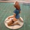
Hi all Please may I present the lovely Airfix Beagle Basset. I have been after one of these for ages and kept missing them on Ebay at silly prices, luckily Airfix came to the rescue releasing this in their Vintage Classics range. Thank you Airfix. I really enjoyed this kit, it is OOB apart from the Seatbelts which are folded over Tamiya masking tape cut to size. Brush painted with Humbrol enamels twice as I rubbed down the rivets for ghat smoother look . The Kit decals went on very well indeed. Thanks tk all that have offered support and encouragement along the way. Hope you enjoy the photos And a few on a base with a back drop. Thanks for looking Chris
- 42 replies
-
- 80
-
-
Does the 1/48 Airfix Sea King come with mounts for torpedoes and depth charges? From what I can see it does not come with the weapons themselves but shouldn't the HAS.1 and HAS.5 have the mounts for them?
-
I started this as a quick and scruffy build while I was deep in two GBs- I thought it would make a nice test article for the aluminium lower surfaces of the F-104G I was building in the Italian Classic theme. In the end I just threw caution to the wind as I wanted to finish the Starfighter, and painted that first- turned out quite well with Vallejo Metal Colour. I only really got as far as shooting the interior colours on the F-80C and painting the pilot, as this photo from a week ago shows. Thinking I’d quickly assemble the fuselage and start a KUTA thread, I soon got a bit fixated on fixing the horrible fit of the intakes, and then the wing roots.. so I had to fill and sand, which lost most of the raised detail. So then I began scribing, then priming, and here we are: Black base next..
- 57 replies
-
- 15
-
-
- Airfix
- Shooting Star
- (and 1 more)
-
 Hi everyone, Here's my next project; the little 1/72 Airfix Hawker Hurricane Mk.1, with the early fabric wing. I've been collecting a few bits and bobs over the last year or so, with the idea of having a couple of engine and gun panels off, to add a little more interest. The Airfix kit is a nice little kit - not quite up to Arma standards, but still the best game in town for an early fabric winged aircraft. I will state up front that I am very much NOT an expert on these aircraft... so be gentle! I have a plan to perhaps finish this one as a Belgian or Battle of France aircraft (noting I'll need to get a two-bladed prop from somewhere, if I want to do the former). A very small start this afternoon - I started prepping the engine bay for the CMK resin engine set. It's always daunting hacking into the nose of a perfectly good kit...! I did think about extending the removal of the cowlings to the panel in front of the cockpit (to scratch build and show the fuel tank), but the CMK firewall is not quite the correct shape to do this, so I settled with only having the front most three cowling panels off, as per the set. The CMK set looks very nice at face value, with some crisp details on the Merlin engine and the firewall. It did take a bit of hacking and sanding to get the parts off their casting blocks (those engine cowls are wafer thin...!). The biggest problem with this set is that the engine bearers are too short and too shallow, which means they don't follow the line of the chin panel. I scratchbuilt new bearers from strip styrene: I also had to shim the bottom of the engine cowl piece so that the nose was long enough to accommodate the engine but still allow the exhausts to clear the fuselage panels aft of the engine bay. A quick test fit: And a quick test fit in the model: Now, the modified bearers are far from perfect, and not quite 100% accurate, but I think this should work reasonably well to give the appropriate impression. I will need to take care as I do a little more clean up of the plastic opening, and as I add details. I'll also need to take care to make sure everything is square on the finished model. As I said, not too much of a start... but it's a start none the less! Cheers BC
- 51 replies
-
- 22
-
-
-
- Hurricane 1
- Airfix
- (and 1 more)
-
The last 3 months have been nothing short of hectic, but with Telford now done for another year and no builds on the bench, I can build something for myself (kind of)! Airfix's brand new Me-410 is up. Massive thanks to Phoenix Scale Publications for providing this kit for a build review for the mag at some point in the future. I never make things easy for myself though as this kit will be back dated to a standard Me-410A-1, rather than having the /U2 or /U4 modifications as modelled in the kit plastic. It's an easy fix, but I'll provide info on that at a later stage. For now, basic cockpit construction is complete with all base colours down. The only cockpit decals used were the ones for the side panels in the cockpit. Everything else was hand painted after the airbrushing of the base colours. these being Tamiya XF-63 and SMS PL179 RLM02. The decals should arrive soon from Hannants and I'll be doing this awesome scheme as shown in the pictures. Invaluable references from the Valiant Wings Publishing book as well!
- 30 replies
-
- 24
-
-
So here I find myself in the Aircraft section with the Airfix 1/48 Me 109 E-3 I don't do wingy things as a rule, and my last aircraft was a 25 year old Airfix Hurricane in 1/24. So here goes .... only 2 sprues! Looking at them, I can't beleieve the size of some of the tabs between parts and sprue. There's a fair bit of flash and ejector pin marks in inconvenient places such as the wheel wells .... 😏 Usual box and sprue shot .... I made a start and soon had the cockpit built ..... Wings cleaned up and dry fitted to check and a coat of grey .... And the same for the cockpit interior.... I'm not intending to do anything fancy with this build ... OOB and hopefully finished in a reasonble time. Comments welcome! Keith 😁
-
Hi all so my next project I am undertaking is one I am very very excited to do. It is the Vickers valiant prototype WB210 conversion for the 1:72 airfix Vickers valiant. The conversion is made by a very talented person, I am sure people have heard of BritJet ( Steve ) it's thanks to him that I can make this absolutely beautiful valiant. I have made a start on this conversion, the first thing is did was to fill in the radome panel lines. the next step I did was to remove the U shaped parts just above the bombbay on both sides then after that I removed the vortex generators from the fin, then the fin intake and then I reshaped the two blisters under the rudder. I actually forgot to reshaped the top of the fin so that is next on the to do list.
- 34 replies
-
- 12
-
-
- Airfix
- Vickers Valiant
- (and 1 more)
-
This build was kind of impromptu. It happened there was an Airfix competition in November and I decided to submit the plane. The initial intention was a RSAF skyvan but it became a Pink skyvan doing skydiving; an idea that evolved as the build progressed. Ground crews in the stash volunteered to skydive and were given masking tape for straps and styrene sheet for parachute pack. Helmet was made from liquid putty. This skyvan build checked one of those model kits that I have wanted to build in my “nostalgia” list. Future build would be the 1/32 RSAF F5E, Airfix 1/48 Hunter (again in RSAF colours), Airfix Bloodhound and possibly the Strikemaster. The model did not disappoint me; I brought back 2 1/48 Airfix kits from the competition. Build link Van in the sky
- 17 replies
-
- 52
-
-
-
- Pink skyvan
- skyvan
- (and 1 more)
-
(510x640)-Copy(95x120).thumb.jpg.33073138e01aa81779639a845926753e.jpg) Complete surprise. They've come up with a Me.410. https://uk.airfix.com/products/messerschmitt-me410a-1-a04066 https://uk.airfix.com/community/blog-and-news/workbench/scale-modelworld-exclusive-new-airfix-messerschmitt-me-410-hornisse-takes-flight
Complete surprise. They've come up with a Me.410. https://uk.airfix.com/products/messerschmitt-me410a-1-a04066 https://uk.airfix.com/community/blog-and-news/workbench/scale-modelworld-exclusive-new-airfix-messerschmitt-me-410-hornisse-takes-flight- 245 replies
-
- 23
-
-
 My local club held a group build recently and the theme was anything from the Airfix classic range. I picked HMS Fearless but, just in case I stalled on it and was in danger of not finishing in time , I also bought the Bristol F2b and Fokker DR1 Dogfighting Double kit. I managed to finish the Fearless, including adding the etch railings and ladders and start this one before time ran out. Looking at the box art I decided to replicate the scene. Here is the box art: and here is the finished kit: Cheers Mick
- 12 replies
-
- 52
-
-
-
- Airfix
- Bristol F2b
- (and 1 more)
-
Almost exactly ten years ago I was given this kit by a generous guy on the Airfix Tribute Forum. Initially, I intended to convert this one to a glider tug. I had built three of these when it was the only IM kit on the block. The first was in my youth and has long gone. The second was built well over 20 years ago with undercarriage down. Not a very good pic, but the only one I have of it. The third one was prior to 2006 and I did that one in flight having found an interesting set of decals for it. So I have previous form with No. 7 Squadron Stirlings. Having acquired this kit, Italeri brought out their Stirling and I thought that might be easier to convert to a tug, (I also got hold of another Airfix one). So the subject for this one changed. If one walks up Gold Street in Northampton towards All Saints' Church, it appears like any other main street around the town centre. There is nothing to make you suddenly stop and ask yourself "What is that and how did it happen?". If you look up at the window sills and the brickwork of the Grand Hotel, you may notice slight damage and chipping. It was caused by a Short Stirling Mk 1 bomber aircraft of the Royal Air Force. July 14th / 15th, 1941. No. 7 Squadron at R.A.F. Oakington, Cambs. Six crews were briefed to bomb Hannover. Their bomb load was to be 30 x 1,000 lb and 33 x 500 lb H.E. and 42 x 250 lb incendiaries. After take-off they were to rendezvous with the main force of 67 Wellingtons of No.3 Group plus 33 Hampdens and 30 Halifaxes of No.4 Group. Of the six Stirlings only one was able to make it back to Oakington. Hannover was heavily defended, and several aircraft were damaged by flak. Their return journey became a nightmare, storms and strong headwinds causing the aircraft to use more fuel than they had anticipated. The Stirlings could not climb above the weather. An Air Ministry ruling that the Stirling's wing span must not exceed 100 ft (so that they could fit into existing hangars) resulted in the aircraft struggling to exceed 16,000 ft. Stirling N6022 MG-D flown by F/O D.T. Witt DFM had two engines shot out, with the third engine misfiring, was planning to ditch in the sea but managed to make the coast just SSE of Norwich. F/O Witt gave the order to bale out. The aircraft crashed at 0340 hrs. at Shotesham Park, Newton Flotman, south east of Norwich. The flight engineer Sgt. J.T. Prentice broke his back but made a good recovery and was later commissioned, rising to the rank of Wing Commander. P/O Keith Deyell DFM broke his ankle but recovered and completed a tour of ops. with No. 38 Squadron. F/Lt. D.A.J. Sanders in N6036, short of fuel, landed at Bircham Newton but overshot and ran through the hedge, fortunately without injury and too much damage. Sqn/Ldr. Speare, also low on fuel, landed safely at Waterbeach. F/O K.O. Blunden landed at Honington although the tailwheel doors were ripped off. Meanwhile, F/Sgt. B.K. Madgwick was coaxing Stirling Mk 1 N6033 MG-Z along with flak damage, navigation instruments u/s, wireless u/s and the aircraft icing up. Looking for Oakington seemed impossible but, in fact, they had actually flown right over the airfield and were now heading towards Northampton. With the wireless u/s, Oakington were unable to contact them and with fuel gauges reading zero, things were looking serious. The flight engineer, Sgt W.H. Robinson had been juggling the balance cocks trying to make use of the small amounts of fuel that remained in the tanks. The pilot, F/Sgt. Madgwick had trimmed the aircraft to fly "hands off", the early autopilots being unreliable. When the fuel pressure lights started to glow red, he checked as well as he could that they were clear of any towns and gave the order to bale out. Unknown to them they were approximately east of Northampton somewhere near Billing and Moulton. Tragically, when Madgwick baled out, he somehow slipped out of his harness. He may have loosened the straps to become more comfortable when sitting at the controls and omitted to readjust them prior to jumping. He fell to his death, coming down in Kingsthorpe recreation ground. His parachute was found one and a half miles away. While descending, Robinson saw the aircraft bank to the left then straighten up but getting lower all the time. He finally lost sight of it as it merged with the dark background, then a few seconds later came a flash as the aircraft crashed and to his horror, he saw it had come down in the town. Robinson may have recognised Northampton as he did come from the area. It is possible that the port outer engine cut because of fuel starvation. That would cause the port wing to drop slightly causing a yaw to the left and if the starboard engine cut out seconds later that would straighten it up but on only two engines would be losing height rapidly. The Stirling came in over St. James' End, in line with Gold Street, losing height until it hit Burtons tailors and the Grand Hotel on the opposite side of the road. The port wing demolished some buildings in College Street, behind Burtons, which now houses a fish and chip shop. The rest of the aircraft, or what was left of it, finally came to rest alongside All Saints' Church in Mercer's Row. Amongst the wreckage lay two unexploded 500 lb. bombs These may not have dropped for two reasons, either a mechanical fault in the bomb release gear or, the release gear was iced up. The two bombs were removed by an R.A.F. bomb disposal team. A photo of this appears on page 95 of "Aviation in Northamptonshire" by Michael L. Gibson. Sgt. W.H. Robinson came down in Abington Park and was picked up by a police car, they wanted to take him to hospital, but Robinson assured them that he was O.K. and requested the police take him to the crash site. He was very worried about the damage they might have caused. Upon arriving at the crash scene, he was shocked to see bodies strewn around Gold Street but, thankfully, they turned out to be tailors' dummies from Burtons. In fact, apart from the pilot there was only one person injured. Ernest Gross was a master carpenter and a volunteer fire watcher had been on duty that night fire watching from the roof of Cleaver's building in Wood St (now demolished as part of Grosvenor Centre site). He was cycling home along George Row when he saw the Stirling coming towards him up Gold Street. He tried to get to Bridge Street but was hit before he could get there. He suffered a broken leg and fractured skull and was off work for 6 months. It was fortunate that the crash happened at 0415 when there was hardly anyone about. It is recorded in No.7 Squadron O.R.B. (Operational Record Book) that the Chief Constable of Northampton, John Williamson, phoned Oakington saying "I can't have this!" I was telling my father about this build yesterday. He was 8 at the time and living not far from Gold Street. He told me that he saw the aftermath. This kit had been started. and I do not know whether it is complete, but the build process will reveal all. I intend to build this, wheels up, in flight, without crew, as it was shortly before 0415 on July 15, 1941. The first missing parts are the seats for the pilot and c-pilot. I remembered having spare seats from a previous B-17 build. They would do as replacements. I had a rummage through my spares and found other parts that came from the Stirling. I don’t know whether I’ll need them, but they can go into the build box for the time being.
-
In the new (December) Airfix magazine is an announcement of a new Scale Modelling show, in conjunction with model railway, at the NEC in Birmingham 27/28 April next year. This is organised by Key Publishing, and I can't imagine that it is intended as a competitor to SMW and the Warley railway show at the NEC. I'm prepared to give it a punt, they are selling advance tickets now on the key underworld web site.
-
Hi all, Inspired by the enthusiasm being shown for the subject in a current WIP I have managed to find the photos of a pair I made a few years back. Like others I found it to be a very enjoyable build but sanded all the windscreen detail off and used decal film instead. Decals came from Siam Scale for the Thai version and S+M for the Argentinian one although I masked and sprayed the blue bands rather than the decal strips. The radar nose came courtesy of the Revell 1/144 Constellation perfect! Painted with Revell Aqua and Alclad Chrome for the engines. Checking my stock levels I still have two in the stash and some decals from Australia courtesy of RAY. This must be on the shortlist for re release! MODeller
- 17 replies
-
- 64
-
-
My (part) set, bought second hand, many damaged, based on: The ARMED FORCES Of WORLD WAR II ISBN 0-85613-296-9 - Illustration 263 Private, British Commandos, 1942. Light raiding order, as worn on the Boulogne raid. A woollen cap comforter, battledress, 1937 pattern web equipment, inflatable lifebelt, toggle rope for scaling cliffs, and instead of ‘ammunition’ boots wears plimsolls. US M1928 A1 ‘Thompson’ sub-machine gun.