

caterhamnut
-
Posts
523 -
Joined
-
Last visited
-
Days Won
1
1 Follower
About caterhamnut
Recent Profile Visitors

caterhamnut's Achievements
")
Obsessed Member (4/9)
1.1k
Reputation
-
Great Build, I have the same 1/12 kit but I ruined mine by melting the front guard and headlamp mounts sadly, I decided I wasn't happy with the paint job I'd done so put them in Tamiya paint remover, and got side tracked, forgot about them till the next day, there were gone, disappeared! I have tried to get them from Tamiya, well they don't even answer emails, let alone offer replacement parts.
If anybody can help me find replacements that'd awesome, or even if someone had the cad file for them, I would love to purchase either.
Thanks for reading, and enjoy this great model.
Cheers Guy's
-

A BIG Rolls-Royce Version II 1-7-2020
caterhamnut replied to Codger's topic in Work In Progress - Vehicles
Just wow. For some reason I’d not found these build pics, despite knowing Chas had built the Rolls.....simple stunning. Two Masters at work....saved for ref! I love the chassis and engine work - the finish and detail is staggering. Going to take some time and go back over this properly when I get a chance! -
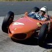
Beautiful build of a pure classic - I am terrified of such paint finish on such a big car - guess that is why my cars have all been 'F1' or narrow-body so far!!! lol
-
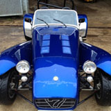
Caterham Superlight - Tamiya 1/12 Custom Build
caterhamnut replied to caterhamnut's topic in Work In Progress - Vehicles
It may not be visible in the photos, but the back of the printed switches have a square pin, which locate in the dashboard holes - so all about the correct location/spacing etc. The holes on the dash are a lot smaller than the switches or dials - which also have a small locating step on the rear. No such thing as a dumb question! -
Caterham Superlight - Tamiya 1/12 Custom Build
caterhamnut replied to caterhamnut's topic in Work In Progress - Vehicles
This car has an FIA roll bar fitted - the kit comes with an old style roll bar you often see on Japanese cars for some reason - and of course the R500's had full cages. I printed this using a slightly different support method for the printed parts - usually you place many small supports, but these can lead to a lot of marks that need to be removed, or worse, 'sagging' of the resin around the parts. So for these thin 'rods' I instead drew a thing 'fin' in the solidworks model - this would provide support all along the length of the bar, and be easy to sand off once printed - it worked well. Test fitting... So that is where I am as of now...the photos below show most of the parts so far started 'assembled' loosely - nothing is fixed into position here, so it all looks a bit wonky! Next stage is probably to aim to fix the engine into place, once I am sure everything else has been done that will be much harder to access once the engine is in. -
Caterham Superlight - Tamiya 1/12 Custom Build
caterhamnut replied to caterhamnut's topic in Work In Progress - Vehicles
Dash - although the dash in the kit is the same layout as this model, the Superlight has a carbon dash - the texture on the dash would have to be removed to cover the dash in a carbon decal - but this would be very difficult to do around all the instruments and switches - so of course it requires drawing up and printing.... I covered the dash in the carbon decal, and then set about the switches and dials, which I elected to make all separately. I coloured and cut tiny pieces of foil to represent the lights within the rocker switches. I drew up the instrument gauges... Still work to do on this - and these parts are just placed, not fixed yet... -
Caterham Superlight - Tamiya 1/12 Custom Build
caterhamnut replied to caterhamnut's topic in Work In Progress - Vehicles
Other bits and bobs: Steering wheel has a central pad, unlike the one on the R500's ....and the interior tunnel top requires sculpting. Handbrake has to be added (not in the kit) I had to make some rubber interior mats... Thanks mate -
Caterham Superlight - Tamiya 1/12 Custom Build
caterhamnut replied to caterhamnut's topic in Work In Progress - Vehicles
After quite a bit of effort.... ...and figuring out how to support the model... The manifold will attach to the block with bolts, as everything lines up - thanks to the solidworks model! But I have not modeled the chassis or panels, so getting all those hard points to line up is a challenge! It did take a few attempts... Once I selected the parts, I added some detail - in this case the lamda sensor... Once I had the fit ok, I painted the exhaust. The main exhaust can will be covered by a heat shield. In these photos nothing is fixed into place yet....just test fitting. -
Caterham Superlight - Tamiya 1/12 Custom Build
caterhamnut replied to caterhamnut's topic in Work In Progress - Vehicles
Model engine update before exhaust and fitting: -
Caterham Superlight - Tamiya 1/12 Custom Build
caterhamnut replied to caterhamnut's topic in Work In Progress - Vehicles
For anyone interested, here is a video of us taking our real car apart (properly apart!!) before a rebuild - this is from about 12 years ago now - but you can see how good the model is in terms of chassis etc etc... -
Caterham Superlight - Tamiya 1/12 Custom Build
caterhamnut replied to caterhamnut's topic in Work In Progress - Vehicles
Right - where were we..... It's been a while, but only in terms of an update - work has been progressing, inbetween a few foreign trips...FB has seen some picture dumps, but not here.... So although a lot has been done, there is still tons to do, with almost every aspect of the car having to be either drawn up in CAD and printed, or scratch built. Very easy to under estimate how much work will be involved - and time....jeez! So I had completed the 'core' of the engine - that is, most of the components were assembled OUT of the car. Things like exhausts have to be fixed to the block AFTER the engine is in the chassis - just like the real thing of course. So I have to determine what needs to be done to the engine AND the engine bay before the engine can be located. I also have to design and model the engine mounts. But without doubt the biggest pain is the exhaust manifolds - despite lots of photos, there is no easy way to get each manifold the correct shape in CAD, other than visually and trial and error - so after learning how to actually draw these up (3D sketches in Solidworks) I started printing off samples. I actually got it pretty close first go, so it all comes together quite well - of course I cannot use the exhaust can from the R500 models - so a new one is drawn up! (I modeled the manifolds on the R500 models with thick solder wire - long before the CAD/3D printing process, so could not use any parts from those...) Before I could work on the exhaust, I had to fit the gearbox (in order to locate the engine in the engine bay correctly) This Superlight has the Caterham 6-speed box fitted, so I made the top plate that will be SLIGHTLY visible from within the engine bay. This now gave me the correct fore/aft fitting of the engine, so I could work on the engine mounts. True to the real ones, these are a very tight fit around the components, such as the exhaust and particularly the alternator. They locate into corresponding mounting points in the chassis rails. So at this point I have the engine location fixed. Now I have to figure out what has to be designed, made and fixed in place BEFORE the engine can be actually located permanently. The exhaust is a 'floating' fit - by that I mean I have to partially insert the engine, then thread the manifolds through the gaps, and bring everything into place as the engine is lowered - just like in 1:1 scale - a right pain in the arrrse. But before that I have some other things to fix in place. Any wiring that may be hard to get too later. A carbon filter on this car (usually removed) sits in the engine bay on the side skin - I drew this up in CAD and printed it - I'll add piping before fitting... You can see the black canister next to the dash in this pic. Quite a big job has been the footwells. The Tamiya kit is based on an older Caterham, which had a short passenger footwell (where your legs stretch out under the dash) - later models have an 'extended' version, which gives more room and usually holds some electrical boxes - in the case the battery - on top. It brings the footwell out to the same place as the pedal box on the drivers side. I had to make this, as the kit has a short version. I tried different methods - plasti-card, folder ali-sheet and in the end a 3D printed version - it was just easier to draw up the awkward shape in CAD than try origami with ali sheet. A few attempts here: The box with the hole in it is the ali kit version, and the hole is for the steering column. I sprayed both boxes to match the rest of the aluminium interior panels. I haven't got a picture of these in situ yet because it requires 5 hands to hold them in place with the bulkhead above, chassis rails etc etc - it is going to be a one-hit fitting process with the engine and engine bay chassis rails! Oh hang on - I have... On to the exhaust.... -
Caterham Superlight - Tamiya 1/12 Custom Build
caterhamnut replied to caterhamnut's topic in Work In Progress - Vehicles
Back to the chassis: I fitted the suspension, front and rear. Nothing much to change on the kit at this point - it is pretty spot on - I tweak the wheel track slightly with the hubs at a later point. The layout and geometry is spot on, and you can actually change the 'set-up' and see the changes if you fiddle with the trailing arms and de-dion tube - I need to video it sometime in the future! I also painted and fitted the diff and the fuel tank.... I added some heat shrink rubber tube on the end of the steering arms to represent the ball joints at the end -
Caterham Superlight - Tamiya 1/12 Custom Build
caterhamnut replied to caterhamnut's topic in Work In Progress - Vehicles
Thanks very much S-B. I'm self-teaching Solidworks, having only dabbled through work - and if you look at what I have done so far, it is all 'push/pull' from solids, then extensive use of fillets - so very much at the simple end of the software😉 -
Caterham Superlight - Tamiya 1/12 Custom Build
caterhamnut replied to caterhamnut's topic in Work In Progress - Vehicles
cheers - Anycubic Photon -
Caterham Superlight - Tamiya 1/12 Custom Build
caterhamnut replied to caterhamnut's topic in Work In Progress - Vehicles
Dipstick! Brass and ali tubing for the dipstick tube, and I printed the 'handle' - another tiny part! of course it 'works'.... So that was the main block sorted - the starter motor goes on after the bell housing... You can see I have also started to add some wiring to the block. But the next big bit to model was the air intake manifold. This was going to be a challenge in CAD for me, but managed it - best way to learn a program is a 'real' project! So the end result works, but it is by no means a 'good' CAD model! The splits involved made drawing and printing it more easily. The throttle is made separately and bolted together after painting, as will be the foam air filter. I don't have this part on my car anymore, so had to rely on photos - although I was able to go and measure some bits halfway through the process - ebay and autofactors are good resources for parts pictures by the way... Test print of the whole air intake assembly, to check fit and scale etc Lots of test prints to find the best orientation etc At this point I glued all the bits together and primed one version, just to get a clear overall view, and again, to test fit! I'll have to move the engine mounts in the chassis! Painted the air intake black, and added some variation in terms of blacks for the injectors and fuel rail etc. None of this will ever be seen again once fitted to the engine! Bolting the throttle on... Rivet! Holding the throttle pot on...(visually anyway) Gradually getting a kit of parts... More wiring... The braided hose is actually black elastic cord... I printed some of the rubber hoses as solids for assembly, as the ones between the head and the air intake manifold actually help to hold them together, and bending rubber tube would have added too much strain...same with the ends of the HT leads - I actually printed them already on the distributor cap. So that's where we are at this point! I printed some different scales for 'future projects' - Blue is 1/8th scale, painted is the 1/12 scale, grey is 1/18th for the Kyosho diecast Caterhams, and the tiny one is 1/43rd! That is 10mm across and I printed it whole to test - it would be assembled separately in the same way as the 1/12th - incredible detail being picked out by the printer though... Before the R500's went, I managed to grab a few quick photos...

