


Ex-FAAWAFU
-
Posts
8,191 -
Joined
-
Last visited
-
Days Won
49
Content Type
Events
Profiles
Forums
Media Demo
Everything posted by Ex-FAAWAFU
-
 Final shot of the strake, this time after painting: Other than that, today's work has all been on the FRB gear - specifically the blade holder (no idea whether that's the official name, but it seems the obvious thing to call the johnson that holds the blades). I have worked out my design, which unsurprisingly will be in two halves. I don't actually have any clear photos of the upper half, but I know exactly what it looks like, so I am not that bothered. You can just about make out from this photo that it is 1. curved to roughly match the profile of the blade (though with a flattish section in the middle); 2. has a hinge at one end (and a fastener at the other, not visible here) & 3. is scalloped on its upper face - you might have to take my word for that last point, though you can sort of see it. As for dimensions, I measured the width from Hasegawa's decals for the markings on the blades, and judged length by eye / proportion with the blade chord [width]. Being white styrene, it isn't very easy to photograph convincingly, but here it is from above: ...and side on: ...and sitting on a blade: Happy enough with that (more plaudits for the round micro-chisel). Once I have built its other half, the plan is to dip my toe into the world of (gasp) casting to produce 4 copies (minimum!). But for now, that's it. More soon Crisp Edit: P.S. the other half is completely different and rather more complicated, but at least I have clear photos of it - you can see the fastener here, too (as well as a very clear view of one of the static wicks on the trailing edge of the horizontal stabiliser - the tail is folded in this picture, if you are struggling to get your bearings!)
- 410 replies
-
- 11
-

-
- Flightpath
- Hasegawa
- (and 1 more)
-
Eduard 1/48 Hawker Tempest Mk.V Early
Ex-FAAWAFU replied to pipthepilot's topic in Work in Progress - Aircraft
The Tempest is probably the least well-known of the Hawker wartime stable - certainly by me! But I do know its descendant, the Sea Fury - originally the “lightweight Tempest” - very well, & it’s fascinating to see glimpses of the future; notably the wing, which is (superficially at least) pretty much identical. And you’re making a lovely job of it, too. -
Navy-ating Bucc's fizz - On the deck at last
Ex-FAAWAFU replied to perdu's topic in Work in Progress - Aircraft
Pretend that the RAF never happened; call 208 by its original name [“Naval 8” - 8 Squadron RNAS]; build a Naval jet. Simples. -
Nice detail shots, thanks - though this particular aircraft annoys me intensely [not your fault!]. It’s an HAS3 with a totally spurious yellow RAF SAR scheme; the RAF never operated the Mk.3, and definitely not in the SAR role... People say it doesn’t matter how museums protray aircraft, yet this mythical scheme is one of the ones offered in the Italeri HAS3 1/48 kit; this is how myths are born. Rant over.
- 2 replies
-
- 3
-
-
- Helicopters
- ASR
- (and 1 more)
-
Airfix Sea Vixen, with some aftermarket help
Ex-FAAWAFU replied to Christer A's topic in Work in Progress - Aircraft
Yes, OK to separate as required. No copies, thanks; just the originals back in due course. Over to Christer re the third question - but my understanding is that he just needs the two wing panels. I sent it because I wanted to keep the sprue together, not for any other reason. -
100 years of the RAF - Silver Linings
Ex-FAAWAFU replied to charlie_c67's topic in Work in Progress - Aircraft
Sorry - I tried! [The cockpit shots might still be useful?] -
Back to the strake... which is now finished (bar the painting). I previously showed you this shot, where the brass base was hugging the Seaking's curves much better than the styrene, and at a better scale thickness. The cunning plan was to use that brass as a ruler and scribe a trench into which to fit the vertical section... which I did, but not without the base coming off! Still, the trench at last gave the vertical section something to grip: I didn't photograph it this way, but it stayed in place unsupported without glue (albeit with zero security). Here we are with both sections fitted: I am much happier with that, and it will look even better under some paint. More soon Crisp
- 410 replies
-
- 11
-
-
- Flightpath
- Hasegawa
- (and 1 more)
-
Jaime, I have only just found this thread, and read it from the start; some really good work on a wonderfully elegant aircraft. Definitely got my attention.
-
100 years of the RAF - Silver Linings
Ex-FAAWAFU replied to charlie_c67's topic in Work in Progress - Aircraft
Can't help with the Siskin, I'm afraid, but these are the only engine / cockpit shots in the excellent (but very hard to find; it was published 51 years ago) "Canada's Wings - The Blackburn Shark" [Karl Vincent]. -
Twin Doodlebills. The Levitating Madonna with the Big Boobies?
-
Wow! It’s been a while since I last caught up... excellent and inspiring
- 331 replies
-
- 2
-
-
- Max Holste
- MH.1521
- (and 1 more)
-
Catapult...?
-
We might have done - it's been a while! Still, that means (if the book is correct) that ZA135 was towed from Predannack to Culdrose in a busticated state TWICE in ten years. If that's true, I'm glad to have survived flying her relatively unscathed!
- 410 replies
-
- 1
-

-
- Flightpath
- Hasegawa
- (and 1 more)
-
Oh, it flew in, all right. Then some Muppet like me broke it, so it had to go home a different way!
- 410 replies
-
- 3
-
-

-
- Flightpath
- Hasegawa
- (and 1 more)
-
Yes, I wondered about the markings, I have to say. I think you must be right. She was only delivered to Culdrose on 7 July 81 - to NASU, where they'd fit any mods needed to bring her up to service standard. Issued to 820 a week later, so they only had 9 months to fit the Predannack incident in pre-Falklands. ZA135 was 015 of 820 for a second time, from 16 Oct 92 until the date of the Predannack heavy landing (23 Nov 92) - but I agree that her colour (RAF BG) and markings (white lettering and hi-vis roundel) definitely look pre-Falklands... plus she has metal blades in the photo, but would definitely have had composite ones by 92. On the other hand, anything (malfunction or damage) that was serious to merit recovery by being towed the length of the Lizard would show up in the records. Still, I agree with you - Lee Howard & Mick Burrow publish mistake shocker! [Edit: by 92 she'd been converted to HAS6, which I think clinches it; this is a Mk 5] Just for fun, here are 3 other pictures from the same episode. If I were better at both figures and landscapes, I'd be really temped to build a diorama of this! [Does anyone produce a 1/48 Cornish pub?]
- 410 replies
-
- 6
-
-
-
- Flightpath
- Hasegawa
- (and 1 more)
-
Oh, they had lots of words, for us... most of which are not suitable for a family site such as our lovable BM! But neither Grubber nor Chockhead is a term of abuse; they refer to themselves using those names, as do Pinkies, Bombheads, Badgers and Greenies (in the FAA...), and Bubbleheads (as you know), Stokers, Jack Dusties, Drain Sniffers, Crushers, Club Swingers, Bunting Tossers & Dabbers in the surface fleet. And I expect I have forgotten several. All military services have a language pretty much of their own, and the Royal Navy is DEFINITELY no exception.
- 410 replies
-
- 8
-
-
-
- Flightpath
- Hasegawa
- (and 1 more)
-
Albatross, Get Your Albatross Here!
Ex-FAAWAFU replied to Martian's topic in Work in Progress - Aircraft
I'm in, too - always enjoy watching a bit of the Martian's lunacy skill. If you have FROBISHER and FORTUNA, assuming they're the same font etc, you have an F, I, O, N & A, albeit with careful trimming. Just saying. -
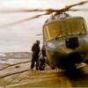
Sorry, Bill - missed this first post of your'n earlier. Part-assembled, yes (though I am a mere pilot; you'd need to consult a proper Grubber or Chockhead expert for 100% certainty!). If I repeat the Predannack photo from earlier, you can see some stowed FRB parts on top of the tractor: the FRB is fitted to Nos 1, 2 & 5 blades, but not to 3 & 4 - not sure why, but at a guess they wanted to keep the aircraft as narrow as possible to pass through the Cornish lanes. In addition to the brakeman whose head is poking out of the window, there's someone perched on the transmission servicing platform to warn if the trees are getting to adjacent to the blades or head, and someone walking along level with the starboard sponson holding a pair of chocks (plus they've taken two tail rotor blades off completely - maybe they were what caused the downbird in the first place). The L plate on the tractor will be because they borrowed it from the "Dummy Deck" (Flight Deck Training Unit, where they teach baby Chockheads). [P.S. Edit: looking at my copy of the incomparable "FAA Helicopters since 1945", the cab in that photo had an "interesting" life. ZA 135. 820 for the Falklands, when brand new. Main gearbox failure at Portland 1985; home by road. Landed wheels up ["momentarily"] during a display at St Mawgan 1986. Heavy landing at Prednannack, collapsing the starboard compression strut [the angled strut from sponson to fuselage side - Cat 3 repair] 21 Sep 1993; home to Culdrose by road [which must be this photo]. "Goffered" [damaged by a wave - also Cat 3] on deck of Lusty during Exercise Ocean Wave 1995 - home stripped, underslung under a Chinook [the indignity!]. Then 10 years as a hack: SAR cab at Prestwick, then 849 HQ, then 820, then back to SAR at 771. Seems to have seen more than her fair share of cack-handedness by aircrew! ZA135 was an 810 cab when I went through OFT and appears in my logbook quite a lot. I did my first ever night deck landings in her.] You can probably see from this shot (my photo, fairly obviously XZ574, FAA Museum Reserve Collection) that the long lateral rod telescopes - the two red marks c.⅓ of the way out from the tail wheel show where to stop when un-furling it, I guess, and there is a pin just by the RH red mark which I assume locks the rod at the right length. You can also see that there is a hinge at the blade end, so when un-rigged the whole assembly would be roughly the length of the shorter rod. Though it's somewhat distorted by the lens and the camera angle, you can also see that the FRB does hold No 3 blade (in this case) quite wide, which probably backs up my theory about why only tip socks in the shot above. [NA39 and Firefly noses + Pup replica in the background] Similarly, the taller supports for Blades 1, 2 & 5 - in this case No 2: you can see the same red lines to show where it telescopes, the same rubber collar (which I think must be to to stop the legs damaging each other when stowed)... ... and here, at the top, the same hinge arrangement. The springs fitted between the blade holders and the rods are to allow a little travel - you don't want it too rigid, because the blades will always move around naturally as the ship does, so it's better that the springs take care of that flexing, as opposed to the blade itself bearing the brunt and damaging itself. I think the ring on each blade holder is how the Grubber opens the holder when he needs to remove the gear - I vaguely recall a tall pole arrangement, though (not for the first time!) I really wish I had paid more attention 30 years ago! [N.B. for any future readers using this as a reference - the blades in these photos are metal blades, as fitted to the early HAS5s, not the composite ones that came into service in ??c.1986, and were thus fitted to the cab I am modelling] This photo shows another angle of the tailwheel. You can see the slot into which the tailwheel lock fits (see above) - immediately to the left as we look of the RBF tag, sticking down below the rest of the fixed portion). Plus the yellow tail wheel unlocking thingy discussed above. I've put this on here, though, because it shows how the rods fitted into the brackets of the FRB - there's a ball at the end of the rod, and a slot in the bracket - you can just about see it here. Also in this shot, you can see clearly how a towing arm fits onto a Seaking tail wheel, and the static discharge wick attached to the tailwheel - in service it would have dragged along the ground. In the background, a folded Wyvern, Royal Marines' Sioux, Jet Provost wing and lots of mangled Barracuda parts! And a Pusser's office chair. Another repeat of a shot you've seen before - the ball & socket arrangement is clearly visible here, too. How many per cab? How long is a piece of string? Assuming preparing to fly, typically one or two guys to remove the FRB gear, tail rotor gust lock, intake and exhaust ECU blanks, anti-icing probe and pitot head protectors, and probably remove the chain lashings, leaving her secured by nylon lashings only. The wheel locks stayed in place and were removed by the pilot during his walk round. [They were always stowed inside the aircraft when you went flying, in a pouch on the wall of the 'broom cupboard', in case you ended up diverted ashore / in a field somewhere and needed to lock the gear]. It's probably worth saying again that FRB wasn't used that often; you can see that it must have been a faff to fit, especially on a flight deck in worsening weather. In normal conditions - e.g. a cab sitting in Fly 1 as the spare, or overnight - tip socks & the TR gust lock would have been plenty to protect the aircraft from damage (even in the calmest of conditions, downwash from other Seakings [and jet efflux from Shars] would easily damage blades allowed simply to flap about). Only if they were expecting really nasty weather would they fit the full monty. I mean this sort of weather [Ark Royal 4, North Atlantic 1975]... ...or this... [Hermes, South Atlantic 1982] Hope that helps! More soon Crisp
- 410 replies
-
- 12
-
-
-
- Flightpath
- Hasegawa
- (and 1 more)
-
True, but that Ark didn’t have a very big flight deck. Dove size, basically.
- 410 replies
-
- 6
-
-
- Flightpath
- Hasegawa
- (and 1 more)
-
The yellow tag is the mechanism that unlocks the tailwheel externally (& it has a RBF tag on it). I imagine it was stowed with the ECU blanks etc on board the ship most of the time, because it really only came into play when you wanted to move a cab that wasn’t manned; the normal way of unlocking the tailwheel was using a handle by the right hand seat. Even deck moves often put a Grubber in the RHS to manage the brakes and tailwheel (if you look a few posts back at my photo - #143 - of the Predannack downbird on tow to Culdrose, you can see his head poking out of the window), but if you didn’t want to do that, you’d use the yellow johnson instead, and have two guys with chocks. The tailwheel lock could only be engaged with the wheel fore & aft, so you always taxied a foot or two dead straight to engage it before take-off. I assume the Chockheads must have done something similar when spotting a cab with a tractor. [Edit:] Incidentally, the tailwheel had a spring built into it that self-centred the wheel in flight if you took off without lining it up first. That way you could engage the lock airborne. We did very occasional running take-offs if very heavy or no wind, but 99%+ were vertical; the lock only really mattered when landing. If a running landing, you really don’t want to have to use rudder to correct for yaw, because it would be incredibly easy to over-correct and (in the worst case) roll the aircraft. Vertical landing also has potential for mayhem if the aircraft is free to yaw; ashore you land with brakes off, but embarked brakes on.
- 410 replies
-
- 5
-
-
-
- Flightpath
- Hasegawa
- (and 1 more)
-
I’m not quite sure where blue and orange and black fit into that, though; when you need 6 colours for clarity on a cold, wet and windy flight deck, I’m not sure that adherence to the International Regulations for the Prevention of Collisions at Sea 1972 is really going to get you very far.
- 410 replies
-
- 5
-
-
-
- Flightpath
- Hasegawa
- (and 1 more)
-
"To Remember The many" The Tamiya Lancaster 1/48
Ex-FAAWAFU replied to The Spadgent's topic in Work in Progress - Aircraft
Many years ago I served in HMS Boxer, and our first foreign port visit (1983, I think) was to Hamburg. We picked up the Elbe pilot at about 2 a.m. and headed on up the river, aiming to reach the middle of Hamburg by about 9. As we got into the river itself, there was a huge floodlit barge with a large crane on it coming the other way, very slowly, in the middle of the cleared channel. The river pilot calmly informed us that it was carrying a 12,000 "Tallboy" bomb that had been found on the river bed, which they were taking [very carefully] out to sea before exploding it. The river was rather tight, and for a few minutes the barge seemed to be heading straight for us. Quartermaster (the sailor who steers) to Officer of the Watch (me): "Sir, do you think they've decided to give it back?" How much we should all rejoice that we don't have to endure what our fathers and grandfathers did! [And now back to the beautiful Lancaster...] -
The inner ones are a bit more complicated than that, Bill - see B below: They are kind of like the outer ones, but cut in half and one part turned through 90 degrees. Which might well give a clue about my working plan for how to tackle them. C
- 410 replies
-
- 7
-
-

-
- Flightpath
- Hasegawa
- (and 1 more)
-
I promised I'd show you what this Connecto malarkey looks like. You will see more of it in due course (not today, though). A bit more on the Forth Road Bridge gear. [It might be worth repeating here that I know that the name makes no sense - if it resembles any bridge, it's the Forth RAIL Bridge... but that's what it was called!] I said yesterday that I drilled the holes in the tail some time ago, so here is proof: The place to drill is pretty clear because the cover for the hole was clearly moulded by Hasegawa. However, whether my drilling or their moulding isn't 100% aligned, from above it isn't quite right if I use a single rod. I therefore plan to use a separate rod for each side. I have tried it, and it fits with no problem. This is a clearer view of the piece that connects to the tailwheel area - though I won't be working on it today, it gives you a better idea of the geometry, plus the colour coding system design to help tired Chockheads / Grubbers to insert the right pole into the right socket. Simples. [The pipe on the right is the fuel jettison pipe]. Lovely rivets! And here two shots of the fittings on the horizontal bar (you can also see the hinged cover for the hole on the side of the aircraft). Today I have fettled the nearer part in the shot above (the one with THIS FACE FORWARD stencilled on it) - drilled a 1mm hole through it to fit my aluminium tube, and done some careful filing to simulate the shape at the top. The inner fitting is a much more complicated shape, and needs to support rods at two angles. Still, I am happy with that as a start. More soon Crisp
- 410 replies
-
- 12
-
-
- Flightpath
- Hasegawa
- (and 1 more)
-
Seat belt clip holder thingy = QRB (quick release... box? buckle? brick?). Nice exhausts. I couldn’t agree more about the scale; how do Bill and them others do it? (And as for 1/144...)
