
Leaderboard


Popular Content
Showing content with the highest reputation on 03/01/14 in all areas
-
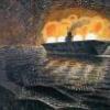
OOB, with Aeromaster decals for Operation Pedestal to Malta.7 points
-
Building log of this miniature is HERE5 points
-
I'd like to wish you all a happy 2014 and also to thank you for all your comments! The project keeps going on..I've finished my 1 and a half Zeros and I've also primed the island and the figures.. Cheers, Panagiotis.5 points
-
Sometime ago I think I posted some pics of my DC-4 build I was doing but not sure where now. Anyhow, over the few days off recently I managed to get quite a bit done including decalling with some custom made decals. So here are some pics: The orange wing tip panels I mixed Xtracrylix Red Arrow red and trainer yellow to get the closest shade I could to match the stills I did from the TV series. Quite a bit of masking was needed all over and in particular for the black areas on the fuselage underside and wing areas behind the engines. The rear portion of the cheatline was printed parallel but needed to be tapered towards the tailplanes..... ... so this was what I did. Cut a section into strips and with the top line persuaded them to follow the curve I needed. The bottom edge was Ok as a stright line. The centre area was then placed completing it. The section over the tailplane was printed with a curve but was too deep and these I also trimmed to fit. The red around the cargo doors was hand painted as the recessed lines were nice and clear and thus made it easy! There were a couple of spare strips and these I cut about to make good various areas, in particular the nose. For all the wing areas and fin, I used my mixed paint from the Dulux range(as on my DC-3 from last year) and thinned with flow improver and brushed on. Since these pics, all the decalling is done with some minor touching up too. Also the undercart and doors have all been fitted. So I just need to add the forest of antenna to the cabin top and repair the white metal rpops two of which the blades somehow snapped off on a couple of them!! Anyone got a good suggestion to repair them or know where I can get replacements!! Naturally I will be trying John Aero first to hopefully see if he has some.... By the way. The model is the MACH kit to 1/72nd!!!4 points
-
Gloster Meteor F.4 VT133/J 74 Sqn RAF Horsham St Faith 1947 - 504 points
-
Sea Lynx Mk.88A 83+21 MFG-3 Norsholz Build for the Lynx Single Type Group Build (Build thread HERE).4 points
-
Moving right along now. Washed and flat coated, and now the exhaust staining. For the exhaust, I used a heavily diluted mix of Tamiya German Grey and Red Brown (90% isopropyl alcohol, 10% paint) followed by an equally thin mix of Tamiya Medium Sea Grey First the Grey/Red Brown mix: Then the Medium Sea Grey: And here it is unmasked and mocked up, won't be long now!4 points
-
I have bought this kit and I too are a little disappointed, it looks nothing like a................................................................................................................................... BEAUFIGHTER!!!!!4 points
-
The first completed kit for 2014. The lovely Airfix P-51D finished in the markings of 76 Squadron RAAF, Japan, 1946. I was brave and filled the panel lines on the wings, and I think it came out pretty well. Finished in Tamiya TS-17 Gloss Aluminium from a rattle can, anti-glare panel in brush painted Italeri Acrylic Flat Olive Drab. Decals were a bonus in a boxing of the Academy P-51 I picked up awhile ago. Photos are taken from the "better side" as I had a few issues with the decals for the codes (broke apart as soon as I looked at them). Interesting comparing it with the Italeri P-51 I completed in the box supplied RNZAF markings over 10 years ago. Thanks for looking, and a Happy New Year to all! Simon3 points
-
Over at another site we're doing a "Then and Now" group build. The rules require two models to be built, finished in the colours of one squadron or company (or its lineal successor) with at least 20 years separating the two. My first pair for this build are a Canadair North Star of Trans Canada Airlines and a McDonnel-Douglas DC-9 of Air Canada. The North Star entered service with TCA in 1947 and the DC-9 in 1967. My models are painted as they would have appeared in approximately 1955 and 1985 respectively.3 points
-
This is the Hobby Boss Spitfire MkV in 1/32 scale. Dispight all the moaning about this kit it is actually very nice although it is a liitle wide around the cockpit it isn't that noticable if you don't stand it next to a tamiya kit. I did use resin replacements by "Quickboost" for the stupidly moulded tail planes (what were HB thinking!) and aluminium replacement cannon barrels, but I have forgotten by whome, sorry. The real issue with this kit is the lack of internal armour for the windscreen, so I simply left off the seperate armoured screen supplied in the kit and sanded off the fairing. I then discovered that this aircraft actually had the external armour, but I had lost the glazing piece so had to leave it as is. Basically, if you want to build this kit then do, the only thing that you really need to correct is the tail plane and you could quite easily sand of the fabric detail and scribe on the correct detail. Oh I nearly forgot, the kit spinner is wrong for this aircraft so I replaced it as well. The best spinner and blades for this, by far, is the one produced by "The Company of Correction" or something like that. Its a Polish company, I believe, and I didn't buy from them because I couldn't work out the cost. I will find the details and post them, a google search didn't turn up anything? Right, the model was first undercoated in white, with preshading added in black on the underside only. The underside was then painted medium sea grey to allow the preshading to show. The upper camo ocean grey (OG) was painted on, in just the areas that need to be OG; the OG was used as preshading then individual panels were tackled using the white undercoat to create a subtle faded look. I then applied my Spitfire camo masks and used the same technique for the dark green. The walk way lines, yellow leading edges, dashed lines under the wings (trestle markings) and over the wheel wells, the upper wing, lower wing and fuselage roundels, fin flash, serials and fuselage stripe were all masked and painted using my own products, using White Ensign Models "Colourcoats" enamels. I always use colourcoats as the colours are spot on. If I have Edgars explanation right then if a Spitfire has a headrest then it would have the IFF wires. No antenna wire though as the HF sets were changed for VHF. For those that don't know the same mast was used, which had the fixing point (the knobly bit) for the old HF antenna wire pully, the "sticky out bit" seen on the Mk I and early MkV. For the IFF wires I used some minute Albion Alloys aluminium tubing to replicate the fixing on the tails and used smoke coloured invisble mending thread for the wires themselves. I just managed to finish this for Telford 2013; it does look a bit better in the flesh3 points
-
I don't post here on BM very often, but I thought it was time to change that. Here's my Airfix Spitfire Mk.XII that I just finished. It was a blast to build, only the landinggear was a bit problematic with the left and right mixed up. I hope you like it. Thanks for looking.3 points
-
This poor thing has been sitting on the dreaded shelf of doom for nearly a year (blimey - how time flies!) so I thought it about time it got some TLC... I've spent the last few days getting her painted up. All paints are Halfords' automotive acrylics straight from the can. Masking the red was the trickiest part, but it's gone ok with only a few minor touch-ups needed before applying the decals and giving it her full 145 Squadron livery: Onwards and upwards... just like a Lightning! Tom3 points
-
On 24th July 1945, S/L R. Harrison suffered hydraulic failure on landing in Corsair IV KD695:143/X, after returning from from a strike on Tokushima Japan. This landing accident was well-photographed on Formidable.The aircraft was subsequently stripped and ditched. Here is my rendition of the aircraft from the Trumpeter kit with LSM cowl and Aires cockpit etc.3 points
-
Once I'd stripped the paint from the Sea Venom, it looked like an unbelievable mess I also had to remove the metal parts, rescribe some of it, and even found that the cockpit had managed to become water logged in the process. So off came the canopy too, and the whole thing looked like I'd slapped it together in an afternoon... Not much fun working on something when the progress goes backwards! So I put it aside for a while... and wondered if I'd maybe picked the wrong hobby. But after a bit of a break I stuck it all back together and gave it a few coats of primer... progress going in the right direction again! Here it is now, using Gunze paints instead... they're so much easier to work with! It's not as nice a finish as I had before, because of all the messing about that's gone on, but it'll do. I've also painted up the Sea Hawk at the same time. I've also done a bit of work on this one while waiting for paint to dry on the other two:3 points
-
Well moved on a bit more with all the main ratlines from ScaleWarship etch, just the smaller ratlines/futtocks once the rigging has moved on. Here are the two main stays/preventers on, still to join the six stays and am going to try to put the zigzag lines on. Useing hemp ropes for most of the thinner stays. Have blackened the hemp with life color acrilic paint. Fixed base of top ratlines, but not fixed the top till I have added more stays. Also re-designing the base as I will need to add a glass surround, so it will be smaller than envisaged. but my wife will paint a background to give it depth. 'Well thats the plan'. Cheers foxy3 points
-
Hi, Usually the appearance of otherwise outstanding builds in 1/12 or smaller is completely spoilt if modelers fit those plastic "wire" wheels of the kit. Even the best kit rims (in 1/24 Fujimi and, surprisingly, Protar) have thick spokes entirely out of scale. You could replace them by aftermarket photoetched parts if you are lucky to find the appropriate size for your project, if you are willing to pay a lot of money, and if you think that adding purchased parts to nowadays almost perfect kits can still be called modeling. Otherwise you might be interested in my following technique. I. What can my technique do? It is applicable to any scale between 1/16 and 1/43. I am sure it works in 1/12 too. The making is fast and, once understood, a routine job. The wheels are delicate but very sturdy. You can replicate any wheel design and size you need. A set of wheels will cost you almost nothing. Last but not least you can say you made them yourself - and that is what real modeling means. You can expect results like these: 1/24 standard rim i. e. with spokes on 2 levels 1/24 racing rim with spokes on 3 levels 1/24 drop center rim 1/24 motor-cycle rim 1/20 standard rim 1/16 standard rim II.The basic principle of my technique When I was interested in 1/35 military modeling around 1980 there were some nice motor-cycle models. They were well-detailed but they had spoke wheels that looked absurd. I found a fast and easy way to replace the thick plastic spokes by real wire spokes. I described it in this German magazine article that was published in 1984. You can see that here the spokes were applied directly to the plastic wheel halves. This technique is okay for very narrow rims as bikes, motor-cycles and and very few vintage cars, where all spokes are fixed very close to the centerline of the rim well, but on all other cars this looks completely unrealistic. This method is so obvious that it seems to be re-invented from time to time. The difference to my technique that I use since the mid-eighties for cars is to remove a radial section of the kit rim including spokes and hub and to replace it by a self-made unit. I described this technique in an article that was published in April 1995 in FSM. Of course I improved my technique in the meantime. This contribution shows my personal state of the art in making wire wheels. III.What abilities are required? This technique is certainly nothing for the novice but if you are able to make simple conversions you will cope with all problems. Some knowledge in geometry is essential and if you tend to miscalculate you might have a problem. IV. Tools required Indispensable is a caliper with electronic or mechanical dial because you have to take a lot of inside and outside diameters. You need a plastic drawing triangle (as you used it at school) for drawing exact angles and a compass. The final appearance of your spoke wheel depends a lot upon how exactly you divide the kit rim radially. You need either a rotary tool with circular saw blade if you have a very steady hand; mark the line on which you intend to cut with a narrow strip of tape (least recommended because least exact). or a self-made construction that could be called "lying fretsaw". You saw here by moving the rim and not the saw. You determine the thickness of the cut by adding or removing those plastic sheets seen on the right side. or a similar self-made construction you could call " lying saw blade" Here you determine the thickness of the cut by shimming the saw blade up with more or less washers. or a converted small drill press with rotary tool and circular saw blade This is the fastest and most exact way. By turning the vertical wing screw you can adjust the level of the saw blade by fractions of a millimeter. Last you need a manual full-size miter saw (stay away from the flimsy small plastic Dobson Miter Rite) for cutting absolutely vertical rings of equal width from a tube. Originally meant for large pieces of material the surface of the "table" is often ribbed. Simply bolt on a piece of angle as I did. You will have to spend about 50 $, but you get a most versatile tool. Besides making wire wheels I use mine almost daily. V. Material required A handy piece of white (scrap) chipboard (or something similar) of 10x10cm up to 20x20cm as a base for a spoke jig. 2 telescoping plastic tubes. The small tube must have an inside diameter slightly larger than the smallest inside diameter of the kit rim. You find telescoping tubes f. e. at Plastruct. I prefer, however, inexpensive plastic tubes sold (in Germany) at house improvement stores or hardware stores in the electrical supply departments; they are meant to protect and to fix electric wirings if these are not covered by casting f. e. in garages and cellars. In English they should be called conduit. If you cannot obtain the suitable small tube you should buy a larger diameter and reduce its inside diameter with a strip of sheet plastic; this is much easier than enlarging a diameter too small. If you cannot obtain the large tube it may be replaced by a stopgap I will mention later. Approximately 50cm of scrap wire approximately 1mm thick If you want to keep the stubs at the ends of the kit axles (meant to bear the kit wheels) you need a piece of metal tube that fits exactly onto these stubs. If you cannot find a fitting tube or if these stubs are too thick simply cut them off, drill holes instead and insert a piece of sturdy wire. Material for your spokes. There are 3 alternatives: 1. At first glance nylon monofilament (= fishing line) seems perfect. It is inexpensive, easy to obtain in many gauges and extremely strong - but it is very difficult to glue and requires additional measures. Therefore I cannot recommend it for my technique. 2. Usually I use copper wire. You find it in various gauges in almost any scrap cable. For 1/24 scale 0.13mm is a convincing diameter. I take this diameter from inexpensive model railroad wiring. One spool at a few € gives enough wires for a modeler's life. Simply strip the insulation this way: 3. Spokes made of copper wire that thin are, however, bent very easily, so you have to touch your wheels with utmost caution. Once bent it is almost impossible to realign them properly. If you want to eliminate this risk buy a spool of stainless steel wire. VI. 4 golden rules for making wire wheels Check if the size of the kit wheels looks correct. If not look for replacement wheels from your spares box or another kit. After spending much time and effort it would be very frustrating to see that your nice wire wheels look odd fitted to the car. If you want to use the kit tyres your wire wheels must keep the original dimensions. Otherwise the tyres will not fit properly. Therefore note down all dimensions of the kit wheel before starting work. Always make a large ( f. e. 10/1) section scale drawing of the planned wire wheel including the hub first. Check your drawing and all calculations several times. This makes annoying planning mistakes very unlikely. Never use liquid super glue. By capillar attraction it wil be sucked into the gaps between the spokes near the hub and the rim well. You would realize the fact that your work is spoilt not before you spray the finished wheel. Only use gel type super glue and apply it with a pointed match. To be continued as soon as possible Please give me some response. I would like to know how many users will follow this topic. This is a very detailed instruction that should give all necessary information. Nevertheless, if anything is incomprehensible, if any questions occur please let me know as soon as possible. This contribution will require more than one evening, so I want to be sure that everything is understandable. Thanks!2 points
-
Happy new year, fellow Britmodellers! After much lurking in the shadows, I bit the bullet, fired up the Dremel and connected up the Ol’ Harder ‘n Steenbeck… and lo, an Airfix Mig-15! (Almost OOB). A little artistic license in the undersurfaces being nice Russian blue prior to the crazy Koreans slathering on the matt black. Oh what fun it is to drill a 0.3mm hole and try and get some EZ line into it… and let’s not forget the hours on the carpet looking for the teeny tiny resin landing lights (so called “pickup pencil” my a**) Albion alloys micro tubes for guns. Airmodel seat buckles and homemade belts: And a complete new jet pipe with throttle body that is now invisible, sigh.. even first time builders succumb to AMS. I learnt a lot: Airbrushing is hard. Resin is hard. Seam hiding is hard. Placing micro dots of superglue is hard. And getting to anywhere near the standard of most of you guys is pretty hard but what the hey, what have I got to lose but my sanity? Cheers Anil PS Best bit was firing up my new Nikon D600 and finding all the images have huge dust/oil spots because there is fault with their sensors...ah well it only cost £2000, whaddya expect for that?2 points
-
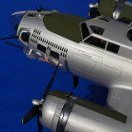
Fairey Firefly Mk.4/5 Korea 1:48 Special Hobby The Firefly was designed as a replacement to the uninspiring Fulmar, and was originally conceived as a two-seat heavy fighter, although it progressed to being much more than that after WWII. The Mark.I reached service in 1944 using the powerful Griffon engine to give it a respectable 316mph top speed and the ability to carry a rack of unguided rockets under each wing for maritime and ground attack duties. After the war the Mark.IV progressed further with the aid of a more powerful variant of the Griffon that gave almost 600hp more power to drive a four-bladed prop, and the chin-mounted radiator moved to the leading edges of the wing roots to improve aerodynamic performance. The Mark.5 added improved avionics and power-operated folding wings, and some Mark.4s were also fitted with this useful device that sped up deployment and stowing on a busy deck. The Mk.5 could be quickly converted between roles to provide support as a fighter, reconnaissance, night fighter or anti-submarine, so became a workhorse of the carrier fleet of Britain and other countries following some export success. It remained in service in later guises until the 50s when it was replaced in fleet service by another Fairey aircraft, the Gannet, which took over the anti-submarine and reconnaissance roles, leaving the dedicated jet fighters to handle the rest. The Kit This edition covers the Mark.4 and 5 as it appeared during the Korean War, where it saw extensive service performing anti-shipping and ground attack duties. The box is standard Special Hobby with a blue/white background and an attractive painting of a heavily-armed Firefly over dense jungle. Inside is a re-sealable bag with seven sprues of various sizes in grey styrene, a bag of resin parts, another of clear parts, and lastly a bag containing decals and a small fret of Photo-Etch (PE) brass. The instructions consist of three and a half sheets of A4 folded into a booklet, and includes a greyscale painting guide that uses Gunze Sangyo paint codes as the key. A QR Code on the painting guide leads to a web page where you can view a colour version of the instructions, including the painting guide, which is a nice addition if you have QR reading software installed on your PC/Tablet/Mobile. The styrene in the box is typical of Special Hobby, and has a very shiny surface and fine engraved panel lines that are together reminiscent of Classic Airframes models, if you remember those. Whilst not a short run kit, it is also not a state of the art moulding, but somewhere in between, although the detail is very good overall. There is no flash evident on the parts, although some clean-up will be necessary to remove occasional minor imperfections in the surfaces of the parts. As with all models, test fitting and adjusting parts will yield better results than just gluing the parts together, so bear it in mind especially when dealing with large assemblies such as the wings and fuselage. There are no part numbers given on the sprues, so you will need to refer back to the sprue diagrams on the inside cover of the instruction manual when it's not immediately obvious where the part can be found. Construction begins with the pilot and navigator's stations, which are separate within the fuselage. The pilot's floor has fore and aft bulkheads added, plus a seat with cushioned back attached to the rear bulkhead along with some additional controls, while the rudder pedals and control column fix to holes in the floor. The navigator's cockpit is built up the same way, but with a deck around his position that has equipment boxes moulded in, and a gap for the addition of a compass on the port side, plus a head-rest behind his seat. The sidewalls of the two cockpits are moulded into the insides of the fuselage, but are augmented by a relatively large number of small parts that are added before the cockpits are added. The pilot's instrument panel has raised detail moulded in, plus a separate compass and gunsight, with a decal provided for the instrument faces on a separate postage stamp-sized sheet. The panel attaches directly to the fuselage, and the two cockpits are added along with the resin exhaust stacks and the tail gear bay, after which the fuselage can be closed up. The smooth chin has a small intake just under the prop, which is built up from an intake and backing piece to avoid being able to see through into the cockpit area, and in the belly of the fuselage, another insert is added with an arrestor hook recess engraved in. You'll need to test-fit and fettle both these parts to obtain the best fit and finish, to avoid having to use any/much filler to make good the seams. With the fuselage closed up, the attention turns to the wings, which have a full-width lower that receives a large slab of resin in the shape of the gear bays, with rib and ancillary equipment moulded in. You will need to trim down some ejector pin turrets that are present inside the wing parts, but the part should then fit snugly within the lower wing, held in the correct location by raised bars around the bay. The wing mounted radiator faces are added to the front of the wing, with separate splitter vanes, and the whole is enclosed by adding the two upper wing parts, after which the radiator fairings are added in front. The wing is quite thick, so shouldn't have any issues with accommodating the resin gear bays, but do check this before you apply glue, as the bay roof is incredibly thin, so can't be ground down. The completed wing is then offered up the underside of the fuselage, and will hopefully be a good fit if you have taken care with construction. The rudder is moulded into the fuselage with the fin, but the elevators are each made of two separate parts that fit into slots in the sides of the fuselage. None of the flying surfaces are separate from the wings or tail, so if you plane on showing them offset, you have some work ahead of you. The landing gear consists of a main strut with two retraction braces at 90o to eachother, and has a separate two-piece oleo-scissor link that is added between the two leg casings. Each main wheel is built up from two halves with nice hub detail, and you will need to take a little material off the contact patch to give the impression of weight if you like that sort of thing. The bay doors are captive to the gear legs, and have small brackets added to their top before being glued to the legs, while a larger outer door attaches to the outer edge of the bay, resting against the leg. The tail wheel is retractable, and operates through closed doors, which are added earlier in the build. The yoke and wheel snap together relying on the flexibility of the styrene, and fit through the hole in the doors into the bay roof inside, as evidenced by the scrap diagram in the instructions. Completion of the airframe is near at hand, requiring only the cannon fairings, some probes on the underside, a clear cover to the wing mounted landing light, and the clear parts, which are thin and clear, with well-defined framework, which isn't too heavy. Each canopy is moulded as a single part, so you will need to do some careful cutting if you plan to pose either of them open, which is a shame given the detail in the cockpits. The large four-bladed prop is made up from keyed blades that fit onto the back plate, with a retaining pin through the centre and the spinner added to the front. Careful gluing could leave you with a spinning prop if that's a thing for you. The Firefly could carry both slipper-type semi-conformal drop tanks on the outer wings, with a stack of four rockets mounted on plates inboard. Their mounting points are noted on the diagram, but take care when gluing them as there is plenty of room for error here. The fuel tanks build up from two halves, while the rockets are moulded in pairs that are attached to a PE base-plate side-by-side. The instructions do give measurements for the rocket plate from the centreline of the wing and inboard of the leading edge of the wing, so it might be as well to mark their position before painting to make the job of attaching them less error-prone later on. An old-school aerial mast is positioned just forward of the navigator's canopy, and will need to first drill out the marked hole, which the instructions show at a slight angle, then run some invisible mending thread to depict the aerial itself, plus the fly-lead into the cockpit that runs down from the top of the mast. The other end secures on the leading edge of the tail level with the top of the hinge indent of the rudder. Markings The Firefly didn't wear too much in the way of varied markings, but it does look striking in Extra Dark Sea Grey over sky, which all four decal options wear. All four also wear wing and fuselage black and white "invasion stripes" as theatre markings, with only one having them straddling the wing roundel, the other three wearing them just inboard. From the box you can model one of the following: Fr.Mk.5 WT488 R-205 Pilot Lt. JFK "Sean" McGrail, 821 Sq., HMS Glory, Korean Peninsula coastal waters, March 1953. FR.MK.5 WB351/K-202 RAN 817 Sq., HMAS Sydney, Korean Peninsula coastal waters, March 1951. Fr.Mk.5 WB416 T-235 810 Sq., HMS Theseus, Korean Peninsula coastal waters, 1951. Fr.Mk.5 WB382 R-206 812 Sq., HMS Glory, Korean Peninsula coastal waters, July 1951. The decals are printed by AVIprint in the Czech Republic, and are in good register, but the smaller black stencils appear a little fuzzy under magnification, although they are still legible. The roundels have separate red centres to ensure that if they're offset, it's your fault, and all the underwing codes have been separated to accommodate the gear bay doors, so you'll need to scratch your head to apply them correctly to the doors if you are posing the landing gear down. There are no decals for the theatre striping, which is just as well, as they can be difficult to get to fit correctly, so a little extra masking will be in your future. Conclusion A very nice package that should build up into a creditable replica of the much-loved, but somewhat neglected Firefly in this scale. Parts clean-up will be important, as is test-fitting and adjustment, but you could say that about almost any kit, even these days. The schemes are samey, but equally striking and are reminiscent of the scheme worn by the flying example that graced the airshows here in the UK until her sad loss in an accident. Highly recommended. Review sample courtesy of2 points
-
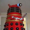
Another missile-launcing sub - the Soviet diesel-powered 'Whiskey Long Bin. This one is armed with 4 X SS-N-13 'Shaddock' anti-ship missiles in streamlined containers either side of the conning tower...... Ken2 points
-
Happy New Year everyone and hope you had a good Christmas. Now the festive seasons over, I thought I`d show you my latest effort, Eduards (Mauve) 1/48 scale P-40, done as a `M` version from the `N` boxing Completed to represent an aircraft of the 25th FS/51st FG, `The Assam Dragons`, whilst based in China Summer 1944 I had been looking for a P-40M kit for a while, when I remembered from a long gone previous build that the Eduard P-40N kit contained the parts to do an M. I didn`t use much of the resin bits as I used them before and didn`t think they were worth the battle to fit them. But I did manage to use a bit of the etched stuff. Decals were from a SkyModels sheet I replaced the gun barrels with brass tube and the bomb came from the stash. Hope you enjoy looking at Cheers Russ2 points
-
I laid the keel this morning, after days of drawing and scaling. Macoma was from the Rapana class; the carriers were originally built as Shell tankers and the structure is quite different from the dedicated Casablanca class or the converted merchantmen from the Empire class; as the ships served both as carriers as well as tankers, much of the original deck layout was preserved and the carrier deck was built over that. As a result the Rapana class did not have lifts; any work on the planes needed to be done on the deck out in the open only for a row of aft deck plates that could be tilted to vertical to give at least some shelter. I only have detailed drawings of the ship as a tanker, thanks to Kees Helder from Helderline.nl As there are no hull cross section drawings from the Rapana class, I morphed, strecthed, cut and scaled the Casablanca hull drawings from ADM on the ship model forum as seen here to match the dimensions up to the tanker deck of Macoma, quite a struggle I have to say, and it remains to be seen if it looks the part. As the Casablanca has a flat stern, I will need to create the rounded stern of Macoma myself, probably by shaping from a block of balsa. I made the mistake of choosing thinner multiplex, and that, combined with the foracious appetite of my rather blunt motorsaw plus my my limited skills, did away with the delicate and accurate measuring and drawing of templates i did for a few days :-( For that reason i choose glueing paste with a bit of filling capacity, to still get strong bonds on uneven surfaces, hopefully later nailing the playwood hullplating corrects any outer dimension mismatch as a result of my plywood massacre. Any way; here she is: up to the tanker deck in frames, drying under the weight of a ton of bricks Also had fun to construct the "super" structure, more a garden shed set off the flight deck dangling over the side and open water, otherwise a swordfish would not clear the deck on a t/o run Finished for the day In the picture below I have temporarily placed the tankerdeck on the level of the flight deck to see if things look right.. De commandersbridge is too far backward here After more sawing and hammering I now have the structural box, which is not strong yet, since the tankerdeck is cut through, the sections weight are now all carried just by the keelplate, and there is risk of breaking. I need to somehow strengthen the box, not willing to risk breaking the thing before the sideplating brings sufficient strength. There is shaping to be done on the back side where the casablanca crosssection template is too wide; can be fixed.. Today was a good day :-) cheers, Skybert2 points
-
On the GR4 the APU is in fact an EAPU ( Enhanced APU). It was uprated on the GR 1 as well because the original APU quite often shut down when carrying out a CSAS Bite. All GR 4's have Fin fuel. If a jet is parked under cover, HAS, RUBB etc, the slats and flaps are set at mid, if outside AFTER inspection by the lineys they are retracted before engine shutdown. Airbrakes were left open all the time, however if outside after engine shutdown & inspection they were closed on EAPU power. Swinging the wings on GR1/4 on the ground WAS A BIG NO/NO. I vividly remember refuelling a Tonka that had Fin Fuel re-instated ( for Gulf War 1 ). normally you hooked up the Bowser, opened the re-fuel cocks and let the jet re-fuel itself. Unfortunately this particular jet decided to fill the aft group AND Fin before the front group, wings and drop tanks. Result? 2 lineys and the Bowser Driver hanging on to the Pitot Probe and me frantically switching off the rear group ,fin and droppers to get fuel in the front group pronto. When loading 1000lber's there always had to be 1 more on the front than the back. The last bomb would be a rear station. That's for 4 or 8 bomb loads. Scoots, Tonka Armourer of 16 years standing. 31 Sqdn GR 1 617 Sqdn GR1B IX( Sqdn GR 1/42 points
-
That's a bit more like it, some proper respect for your elders and betters. Dealing with the fuel tank issue first, from the operating manual I can identify the fuel filler hatch is here: Which on the cut-away drawing means its this rectangular thing under the gearbox: I suppose its near to the C of G there, avoiding trim issues as the fuel is used up. Those American's can be damn clever sometimes, my dad always said they are good engineers. I added a few more bits and bobs of detail to the end bulkhead and declare it finished: I then finished off the rest of the framing in the rear compartment, It is rather simplified compared to the real thing but hopefully conveys the right sort of impression Not much will be visible when the fuselage is closed up anyway: I then flared the end of some 0.5mm tube using a combination of my pin tool and my smallest reamer. I also put a point on some copper wire: I don't know how I ever managed without these reamers, a good buy and highly recommended (especially to milktrip if you don't already have some) That all gives a nice positive location: I drilled the fuselage and used the reamer to insert it, (my carpet monster is withering away, poor thing): Followed by a bit of glue I now have a nice pair of downward pointing drain tubes: Just like the real thing!! This back end it nearing completion (in that it will be ready for some paint soon). I need to have a think about what to do next.2 points
-
Blimey Mark, even the diagrams of your plan are things of beauty . Looking forward to this. Cheers Steve2 points
-
Managed a bit more work on the Lynx this week Since my last post, I had it pointed out that the sand filters were not fitted to the IFOR Lynx (Thanks Tony), so had to chop them out and use the normal intakes/filters Next up was some detail work on the inside of the cockpit glazing, blue tint, frame painting (with the help of the Montex masks), overhead console (eduard) and a representation of the lights at the rear of the cab. Dry fit to the fuselage The inside of the doors completed with some help from eduard and Montex And finally for this week, the starboard TOW assembly. I have it in good authority that the IFOR birds only had the starboard fitted and only the outer tubes loaded Taking a break for a week, family skiing, more when I get back...2 points
-
I've used Xtracryix for years. I never quite know what is going to come out of the airbrush. It all adds to the excitement. I've also started using Tamiya, but with boringly consistent results.2 points
-
That's a little jewel, Milktrip.2 points
-
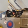
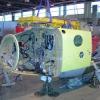
That is absolutely Superb the MR head is stunning. The colour coding is used to identify the blades yellow being the number 1 blade and as you said correctly used for tracking and balancing as well as identifying which blade fits on which sleeve when they are removed for maintenance/ transportation. The little coloured pots on the blade sleeves are used to house lead shot that can be added or removed to balance the MR head, and you have modelled it superbly. Awesome Job.2 points
-
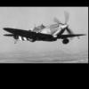
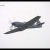
Call that low? This was low. (Passing the tower at Duxford)2 points
-
As others have said, the first solo has to be top of the list! Mine was from Lydd in a C152, G-OBAT with Cinque Ports Flying Club. The rate of climb was certainly impressive once the instructor had got out! I flew the JSPC BN2T Islanders for a while in Bad Lippspringe and had a few joy rides in helicopters, but the best by far was a ride in a CH-53 although I did get rides in Lynxes and Gazelles, all of which were brilliant fun. A few years ago I hit an aviation milestone and clocked up 10,000 hours. There was no way I was going to do my 10,000th hour in an Airbus, so decided to go to Kemble and do the magic number in a DHC.1 Chipmunk, the first aircraft that I had 'flown' as an ATC Cadet way back in 1978 from Manston. But my stories are boring compared to the many fantastic experiences that many of you have had. I'm extremely envious of anyone who had the chance to fly in Concorde or fast jet formation flying!2 points
-
to represent more intensive, black smoke trails i used tamiya's flat black with a strogly thinned xf-1 i made delicate smoke trails at MGs area seeya in a gallery!2 points
-
This is the only photo I have I'm afraid2 points
-
i'm glad that you're like this s-b-s i added some more paintchipch and scratches on the paint. this time i used thin tweezer's end to damage the paint coat and expose silver base to make some dirt on the foselage sides and the wing i used AK's enamels. First i airbrushed a 'mist' of enamels on some areas. next I rolled them over the surface with a cotton bud slighty weted with white spirit. i also airbrushed some mud patches next to the wheels The process of creating the exhaust staining began by airbrushing some fine smudges with slightly diluted AK's track wash2 points
-
If you DONT LIKE IT DONT BUY IT !!!!!2 points
-
Started in 2011, it's the first model I've completed in 2014! My personal KUTA campaign is continuing.... The Revell kit built from the box with no additions apart from rigging. It's a great kit to build and really enforces Revell's recent resurgence as a quality ship kit producer. Painted in WEM Colourcoats over Halfords primer. Weathering done with oil paint, Tamiya Weathering powders and pastel chalk. The sharp-eyed will notice no naval ensign and no propellers in the home made photos. Both were added later when the top two pics were taken at our club by Mr C Bradley! I decided to weather this one having seen the fantastic models of submarines posted in recent weeks. Not to draw comparisons, but it was worth the effort to get the look of the finished article. I chickened out of weathering the wood deck and just left it in the Schlickgrau base colour. The bad pictures were taken with mobile phone as ever. Happy to answer any questions about this one.1 point
-
No words, only emotions...!!1 point
-
Nice job, can't believe you built it in 11 days! Julien1 point
-
Ta for the heads up, hadn't realised we did our own PW's back then.1 point
-
Well done thus far Nigel, I think you are slowly getting the required effect for the engine bay. Martin1 point
-
Thanks, guys! I thoroughly expected to bin it by now, and if it wasn't for that Group Build, I wouldn't even have started it. But it's been a lot of fun. I see that there are three 1:72 Anigrand B-32 Dominator resin kits on eBay right now, a mere $115.00 each. Wifey won't let that one happen. So how about you guys crowd-source some funding for me, then I'll buy one of those bad boys and do a right proper WIP here on Britmodeller? I'll get the Matchbox/Revell PB4Y-2 someday (I think my LHS still has one of the Revell kits on the shelf for $33). The review in Detail & Scale dissed the entire model, stating "shapes and outlines are inaccurate from nose to tail, and moldings are heavy, thick, and tough. It is so crude and inaccurate that it...is not even close to correctly representing the real thing." Really? I think it looks quite nice when built up. Linky. If I were to go crazy counting rivets (who, me?) I can get the Cobra resin correction set. Cheers, Bill1 point
-
wow, realy great looking P-40.. i like the feeling your kit gives when you look at it.. what colour did you use for the chipping? as it looks smooth and natural.1 point
-
Nice job, she looks really good. Sorry to hear about the masts,1 point
-
Good question. Having removed all from the base of the hull, you could find a nice piece of wood, give it a good varnish and leave room for the name plate. The ship could ether free sit on this or you could find some dowels that would make a nice plinth to support your ship. The dowels would be glued to the base/wood and the top of the dowel fixed to the hull of the ship, its all a question of what you want to finish the ship on. Most kits come with a base of some sort, thats why you had those lugs on the hull to fit such a base. If how ever you are not going to use the base that comes with the kit, then you have to scratch build one. Cheers foxy1 point
-
Super build, that looks great. A pity about the bent periscope array, but far less worse than running aground! It looks great next to the Trafalgar class sub.1 point
-
I suspect that is a classic instance of why engineering drawings have "Do Not Scale" on them.1 point
-
Perhaps this will help- something I did for a friend who wanted to know "the basics", with some attempt to bring it up to date: Yes, but what can I make from this kit? (48th-centric) Disclaimer: I am focusing on the basics here- nose, core fuselage, tail, wing. There are many detail differences, some of which I will mention, but first we have to get the right combination of big pieces! * First group: The original single-speed Merlin types all have essentially the same fuselage (tip to tail). All had a fixed tailwheel. Various different props were fitted, and there were several different exhaust configurations. The engine’s air intake changed slightly with the Merlin 45, and tropicalisation is an obvious change. The pressurised Mk.VI has some subtle but important differences, most obvious being the hood and the deletion of the entry door, plus the intake on the side of the cowl for the air pump. Seafires (and hooked Spitfires) have the A-frame hook in the belly. Some PR birds had a deeper chin, and almost all had a different windscreen. To this common fuselage you must add the wing of your choice: ‘a’ wing: 8 .303s ‘b’ wing: 2 20mm (drum fed) and 4 .303 (the bulges for the drum changed shape a bit somewhere along the way) PR wing ‘c’ wing: normally 2 20mm in inner bays, stub at outer bay, 4 .303 (the inner of which moved one rib-bay outward compared to a/b) gear legs at different angle, gear door is “dished” instead of “flat” (that is, following the curve of the wing). All have the asymmetrical cooling. With the Merlin 45 the oil cooler was deeper with a round intake, instead of the half-round of the Mk.I/II. The Trop adds a flared exit to this. Because of the differences, it makes sense to choose an appropriate wing, even if you have to transfer it to a different kit’s fuselage, rather than convert (except perhaps the PR wing- easiest to start from would be the ‘a’, but the Airfix PR.XIX gives a new possibility since I originally wrote this). Scribe the wing-fold lines on a ‘c’ wing and you’ve got the Seafire III’s wing, but there are a number of detail changes required for any Seafire, and none of the kits claiming to be a Seafire do the work for you- they’re just hooked Mk.Vs! [Airfix Sea 17 provides another possibility, with some work required.] Stick an early Griffon nose on a Vc (and change the rudder) and you’ve got the Spit Mk.XII. Later ones had the retract tailwheel. * Second group This time we start with the ‘c’ wing, but with symmetrical radiators. We actually have two structurally different ‘c’ wings- that of the IX/XVI was an evolution of the Vc, while that of the VII/VIII/XIV came directly from the Mk.III. These had shorter ailerons and leading-edge fuel tanks inboard of the cannon. There’s also the PR wing, which now has the gear angle of the ‘c’ wing, and the Seafire’s folding wing, with leading edge tanks added, but still the longer ailerons. Now select the fuselage of your choice: 2-stage Merlin 1-stage Griffon 2-stage Griffon High-back (PC) VII (PR.X) - (PR.XIX) High-back IX/XVI, VIII; PR.XI Seafire XV XIV (early PR.XIX) Low-back IX/XVI Seafire XVII FR.XIV/18 One important change that comes with the 2-stage Griffon is the larger fin (with retract tailwheel). The radiators are also deeper than those for the Merlin. The armament changed to ‘e’ configuration on the IX/XVI and XIV, but it was still the same wing. The 18 had a different arrangement of skinning, so some rescribing is required to be strictly accurate if making one of these. * Third group Now take a high-back 2-stage Griffon fuselage and stick the Mk.21 wing on it and you’ve got, oddly enough, a Mk.21, or with some further tweaks a Seafire 45. Note that the radiator housings on the 21 are somewhat different from the XIV/XIX ones. (Stick a Spiteful wing on the same fuselage and you can do NN660, the first prototype.) Using a low-back yields a Mk.22/24, but by the time these were in service they had the Spiteful tail, as did the Seafire 46. Finally, the Seafire 47 with folding wing and larger flaps. It may also have a bigger bulge on the upper wing surface to clear the wheel, but I’m not completely sure about this. Then there’s the Spiteful/Seafang. After the first prototype it had the new fuselage but still the Griffon tail. Subsequently the new larger tail was fitted. Take essentially the same wing and put a jet fuselage on it and you’ve got the Attacker. If that isn’t enough, you can do a I, V, or IX on floats (they even thought about an Attacker on floats!). Postwar there was one VIII and twenty-some IXs converted to a two-seat trainer configuration, with regular cockpit moved forward and a second grafted on behind with raised bubble. There were (and still are) some different two-seater field mods. Prototypes/ testbeds, for the more adventurous, would present some truly unique looking subjects (Mk.IX with XIV fin and contra-prop, anyone?) bob1 point
-
The YF-12's real operational requirement was to serve as disinformation and distraction. Oxcart was a spyplane first, last and always. The existence of the YF-12 was revealed to lull Soviet agents into seeing what the US wanted them to see, so if a Soviet agent came across intelligence of a Mach 3 aircraft, or parts and paper trails thereof, that agent would write it off against the seemingly dead-end YF-12.1 point
-
Ok, let see next stage of work on the tail section.1 point
-
Pushing forward I decided to make completly new coolers and radiators inside. There are two reasons behind. First is wrong shape and diamentions of kit parts, second - I tried to check how close to the real thing I can achieve with own photoeching. First I remove kit parts. Then I put into wings internal upper surfaces of coolers. I used styrene sheets and Gunze epoxy. Coolers fairings I also made from styren. At this stage I didn't profile external edges. This is the heart of whole thing - etched radiators. Each of them had almost exactlty the same number of holes in the grid as the real Spitfire! This was the test. Result was big supprise for me. Radiators with grids inside, painted Alclad. Then I put whole elements in recess and profiled edges. Ater all with Gunze epoxy I profiled fairings fillets. As you can see, there is some more work on bottom side of the wings. Finally radiators flaps which are handmade - not etched. I'll put it on right place after paintjob.1 point

.thumb.JPG.3498f40362ff13ebfc4b2e45abbd545e.JPG)


.thumb.jpg.d17ff607fc7e89ed057e63fcb6f2a888.jpg)


This leaderboard is set to London/GMT+01:00