
Leaderboard


Popular Content
Showing content with the highest reputation on 14/08/12 in all areas
-
This has probably been posted before but I've just seen the photo below at this site and thought it rather funny! Mike .5 points
-
3 points
-
Wall Mounted Vertical Paint Rack and Travel Workstation Progressive Engineering Earlier this year I received a sample of the new Wall Mounted Vertical Paint Rack and the Travel Workstation produced by Jon Page and his company at Progressive Engineering Progressive Engineering produce, laser cut, self assembly, MDF stands, holders and racks to hold modelling paint jars, pots and bottles and have branched out into workstations to keep your desk organised (sometimes a quest too far for a modeller). As ever the simplicity, practicality and elegance of their designs are readily apparent and the fact that Jon is an accomplished Figure Modeller ensures that whatever is designed and produced is normally one of those items that quickly finds a well used place in my set up and has me thinking why no one has ever thought of that before? Wall Mounted Vertical Paint Rack This item is designed to hold paint bottles and jars in an offset from horizontal fashion (to prevent them from falling out) and is secured to the wall of your modelling room. The sample I received was sized for Gunze/Tamiya (Small) paint jars and in total could hold 55 Jars. It comprises of 4 laser cut MDF Shapes (a front, back and two side pieces) and a bag containing all the necessary nuts, bolts and washers to assemble it. The attention to detail is such that all the components are clearly marked with small laser cut arrows to aid orientation during assembly. There are even a couple of small screws and rawl plugs to enable you to wall mount it when complete which saved me digging around my DIY kit. Assembly took less than 5 minutes with the included allen key in the nuts and bolts bag: Having had a set of cupboards made for holding paint, this is a far more simpler and dare I say it elegant solution It will be mounted directly above my modelling desk and the design makes it easy for me to quickly find the required paint colour when needed. Travel Workstation Having spent a good part of my adult life in various parts of the world, one of the great difficulties has always been finding a bit of space to indulge myself in a bit of muddling. Like a good few of us, the fallback method has been to use a tea tray. However it does have its drawbacks in that the flat surface means that space is at a premium and you balance the paints and glues at your own risk. Our very own Skii can vouch for those inherent risks after an incident involving a suite and a bottle of black paint. Jon has come up with a travel work station that holds in my example an A5 cutting mat (supplied as part of the set), a number of paint pots/jars (the kit contains 3 x inserts for Andrea/Vallejo, Humbrol/Foundry, Tamiya/GW hexagonal Non-specific) and paint brushes. What I really like about the workstation is that you do not require tools to assemble it, it is held together by silicon O rings which is another piece of engineering elegance from the company. To complete the package, it is all contained in a plastic A4 file envelope, therefore making it easy to sling in a suitcase or laptop bag to accompany you on your travels, be it from hotel rooms or even your own living room in front of the TV. The customer service and can do attitude of Progressive Engineering is second to none. Progressive Engineering have an ebay shop (link is on their webpage), you can also order direct from them and I would recommend this if you want to specify any changes such as brush holders or size of paint bottle/jar. Progressive Engineering Solutions Ltd Highly recommended. Also reviewed previously - Custom Paint Jar Stand Review Sample courtesy of Progressive Engineering Solutions Ltd.2 points
-
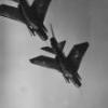
Jonathan Whaley brought Miss D past Beachy Head very low, very fast and very close John2 points
-
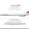
Hi guys, here is my first jet build and follow up, a Sea Harrier FRS.1 As a harrier enthusiast, I had a lot of fun with this build, though it took me quite a bit of time, 8 months of work in fact. Decals are half real and fictional, a mix of the Italeri and Hasegawa ones. Made a mistake there, as although the Italeri whites had a much better tone than the Hasegawa decals, their coverage was utterly horrible. And some harrier literature to round it off! More pics and larger sizes can be seen here: http://www.flickr.com/photos/df0084/ http://www.flickr.com/photos/df0084/sets/72157629541671750/ Thank you for looking, everyone!2 points
-
John Lennon said, that we are the eggman. I thing, John was thinking about man like me. I build the model of Columbus karaka Santa Maria. The basic element was eggshell. English man like eggs, and I hope You join this build. Painting and making stuff using eggshell is a Easter habits. But making models using eggshell is special habits, which was born I polish modelers forum nPWM. There is a short report from building. I ‘m sure, that photos tell more than words ( writing in English make me angry, because I ‘m “bloody foreigner” ,-)) And the finale effect1 point
-
I've got a soft spot for those 80's stealth wonder concept planes, and luckily I managed to find Italeri's rerelease of the MiG-37 Ferret. The last time I saw it was 20 years ago in the stores so wow, the memories! Proof! The pics are from when it's come along a bit, but the you can clearly see the strange shape of the design. It looks like half a dagger, half a duck and half a bat. The kit also comes with no to little raised panel lines so this gives me some fun to play around with. The horrible wing join is dealt with by using a superglue filler. Nifty. The only weapons that comes with is an oddly shaped bomb and a poor 80's representation of a russian air-to-air missile. I will be replacing them with more accurate AA-6 Aphids from my departed Revell frogfoot model. Eventually I plan to modernize it by giving a recent T-50 style splinter camo, which I think is fitting. Thanks for looking!1 point
-
Here is my Academy 1/48 Golden Eagle, built for the Aerobatic GB. It is a viceless, well-engineered kit. The most time consuming part was the decal placement. I really enjoyed this project and it will most definitely take pride of place in my cabinet. As you can see from the pictures, I forgot to stick down the back-seater's instrument coaming, but it is all sorted now. I also need to clean off some of the dark wash from the wheel hubs. The WIP is here: http://www.britmodel...topic=234922382 And finally, to give an impression of size, here it is with a 1/72 Airfix Hawk:1 point
-
Wingnut Wings OOB with Tamiya paints, rigged using ez-line.1 point
-
I finally finished this the other day. Overall it's a very nice kit, although it needs a little care. The engineering and the breakdown of parts is a little more complicated that strictly necessary, presumably because Revell will be releasing further versions. I certainly hope they will be anyway I'll post more pics in RFI in half a mo!1 point
-
I will talk john ref 1/72 scale but it will be very small this is his likley response!! I will keep you informed Regards Robin1 point
-
There's a lot of sense being talked here about pre-shading, which seems almost to have become "de rigeur" for some modellers but I've never found it convincing (quite attractive in a toy-like way, but not convincing). The master of weathering as far as I'm concerned is Chris Wauchop, who often works with Brett Green. As he says, subtlety is the key to successful weathering but too often it's over done. Max1 point
-
Yes it is confusing because of the re-painting after delivery. Where Col says above that "The Mustang Mk.IA as well as the Mk.IIs were delivered in NAA factory equivalents of the DFS" I think (I hope!) that he means TLS. Then "After reassembly in the UK, they were stripped and repainted into a standardised pattern in DFS colours." I don't know why the change in factory painting from TLS to DFS was so late but perhaps it had something to do with changes to the planned use of the Mustang? David Muir writes (in Southern Cross Mustangs):- "Allison engined Mustang Mk 1 and Mk II deliveries to the RAF were finished in this pattern (NAA pattern for early Mustangs ) using "Temperate Land" scheme colours (i.e. Earth/Dark Olive Drab/Sky type S) reflecting their primary RAF role of Army Cooperation. Early MK III deliveries seemed to follow Fig 1 and Fig 692-b (the NAA diagrams) that specified Earth as the spinner colour." The early NAA diagram (Fig 1) shows both TLS and Desert scheme with the note:- "Except for insignias, entire lower surface of airplane is azure blue for desert scheme and sky type s for regular scheme. On desert scheme only spinner is sky type s". The re-painting occurred because by the time the later Mustangs were arriving in Britain in TLS the DFS had been introduced almost universally so the aircraft were re-painted in standard MAP paint colours of British origin. This is the scheme David identifies as RAF2 or "Loop" scheme:- "This pattern appears to have been created and applied from sometime in 1942 in the UK when the factory 'Temperate Land' brown/green camouflage was repainted to convert it to the 'Day Fighter' grey/green colours." The factory changed the painting during production of the C model late in 1943 or early 1944 and these aircraft, in factory-applied DFS are identified by David as RAF1 in the equivalent ANA paint colours. So the basic question to be asked is "Is my proposed Mustang in re-painted MAP DFS or factory equivalent DFS?". American Sky colours were not a unique paint colour but paints produced by different manufacturers to meet the British requirement, originally, for "duck egg blue". Therefore they were equivalents to MAP Sky, of which Dupont's product 71-021 was only one such. Again is it important to bear in mind that paint colour standards, e.g. the master colour swatch, were not always reflected precisely in the manufactured paints because of inevitable variance. This still happens with paint and was happening in the Ford motor company just a couple of years ago. The variance is often impossible for the human eye to discern unless examples are compared side by side under the same illumination. In other words if you looked at aircraft A in a hangar and then went outside and looked at aircraft B on the runway you might assume both were painted in identical Sky colours, even though in fact the two applied paint colours might be slightly different because they were applied at different times from different batches of paint. After paint variance there is an inevitable degradation in the paint surface. In the wartime period the most common occurrence was chalking where exposure breaks down the microscopic top surface of the paint and "frees" the pigments to become a variegated dust or patina over the surface, often confused for "fading". This was especially prevalent in paints with a high white pigment and/or extender content, such as the various greys, and resulted in a patchy greyish white patina making the colours appear lighter and weaker - or "faded". Although it can be hard to see it is visible in many wartime colour photos if you know what to look for. This degradation is often accelerated by the combination of extremes of heat and moisture as in a tropical climate. It was supposed to be countered by airframe maintenance but again time and circumstance affected this. Genuine fading (and other degradation including colour shifts) is caused by a branched chain reaction in the paint structure caused by thermal, photochemical, photophysical or high energy radiation initiation. It is not possible to reduce these various processes to a simple "rule" as they are holistic, cumulative, eccentric and material, circumstance and factor dependent. Especially some paints (on the same airframe) might demonstrate drastic degradation whilst others do not. As well as providing colour the whole manufacturing process is geared towards creating coatings that are resistant to this degradation and which provide resilient service in protecting the underlying metal and maintaining an acceptable appearance. Sorry for this sidetrack but the question was asked on another thread why Japanese paints were so "poor" and peeled so badly. Generally they weren't. Japanese factory lacquer paints were usually of very high quality but the problem was that for most of the war the (Army) camouflage paints were being applied at Depots not factories. The war situation was such that where replacement aircraft were required urgently they were often painted hastily without proper surface or paint preparation and more significantly without a primer being applied. Once those aircraft were exposed to heavy service in a harsh operating environment of tropical sun and torrential rain the results were inevitable. It wasn't the quality of the paint that was the problem. One can track this by noticing that aircraft delivered to units outside the campaign season (during the monsoon period) or when they were re-fitting or working up were painted to a much higher standard of finish (and camouflage) simply because there was more time to do so. The typical Army scheme of green mottle over natural metal was expedient, to get the aircraft to the front quickly with the expectation that it might not last long there.1 point
-
Hmm, some very interesting points being made here but were the Aufklarungsstaffel not still under a German command? Perhaps that Me-262 was the German commanding officer's personal machine? German machine, German crew, Anti-Soviet markings? If nothing else it will be eligable for the What-if II GB1 point
-
this thing is totally fantastic. love all the work to make it a trolley. awesome keep up the awesome work...1 point
-
Back to the updates after a rest in Japan! In the meantime, here's what I've done. Weapons, the AA-6 Aphids have been completed. It'll look better further away. I promise. As well as that futuristic looking russian laser guided bomb. It was much to plain so extra panel lines was added to spruce it up. In fact panel lines seem to be the ongoing theme here. Being plain as all hell, I decided to take this opportunity to have some fun with them. Any mistakes are easily cleaned up with an application of Super glue which has the added benefit of making you high with it's fumes.. It's my new best friend. One thing I'm not looking forward is cleaning up this join between the intakes and fuselage. The main remedy is to recontour it so it'll be on the same level at least. With this, my pile of completed parts keeps on growing!1 point
-
Yes it is looking good. Bye the way it is poundland selling the primer I grabbed a couple today thanks for the tip!1 point
-
Hi I´m starting this 1:72 Twin Otter from Argentina Air Force. I have the intention to make the "T-82" involved in a mission of rescue and evacuation of a pilot shot down over the islands during the conflict. I like Matchbox models and this seems quite acceptable.1 point
-
AS she was scuttled in Loch Ryan - a sea loch - I wonder if she gets dived on at all? Edit - since found this http://www.divetheworld.com/diving/warbirds/SunderlandT9044/index.htm1 point
-
Progress Long hours yesterday ......and ended up here..........today Decals left with stencils then wash and the final stage.......pretty decent fitting kit with minor issues and not too many steps....... All silver work with the various gunze/gaia and alcad....... Best Regards Mr B1 point
-
After the wall on this is pretty well advanced, I am slowly beginning with the "work equipment".First of all I soldered brass L-profiles to 6 frame carriers.Then I put a metal broomstick with the Dremel and a cutoff wheel to the correct length.This recreates a pipeline.I have placed these components on the Dio for a test. The tube is damaged still on the crack of the wall.A walk for the maintenance of the pipeline is fixed on the frame base.Other tubes and pipes are still complemented.Here the images of test. Meanwhile, I have soldered a metal section of the wooden planks .... I will never electronics technician - what a botch.For a Test, I have fixed the wooden planks.To get an idea of the size, I put the figures into the hallway.1 point
-
Now to the brick walls. First I glued two-sided tape on the wall, then rolled a band modelling clay with the rolling pin. Straightens the edges with a knife and carefully dissolved the mass with a spatula from the surface. The "pancake" was carefully adapted to the existing tile layer and then pressed, that the mass is held by the tape. Then adjusted the edges with a knife. With a metal ruler I pressed again the horizontal joints - at a constant distance and pay attention to correct horizontal alignment. Then I pressed up the vertical joints with a nail arrows (tool is no matter, have taken the nail arrows only because the correct joint width). Edit always a little joint, in order to develop an irregular floor base. When the area of joint was fitted, here and because different tiles have edited I, i.e.: crisp on the surface and this withdrawn to simulate damage (hard to describe, was feeling). Finally it was adapting to the broken edge. A small lump was modelling clay knocked flat and cut into strips. The strips were cut into small pieces. One of the pieces modelling clay was then put on the spot and varnished with a knife with the adjacent tile of the wall. Then, the joint was drawn to. Appropriately, the length has been shortened and then the rest adapted with a knife to the broken edge. I hope I've expressed myself not too cumbersome. Here the images:1 point
-
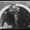
Thanks for the encouragement Tim Anyways Pressing on Got an update.......... I redid the belts..................and finished up the cockpit and gun bays........... Used Mike Grant decals as the decal provided was too advanced for a thunderjet... Started putty work on the wings and fuslage......did some test fitting and the gun bay cover cannot fit.......and the windshield......also cannot fit....so some playing around is needed......but gun cover is because the ammo belts are not sitting well.....so its going to be left open the easy option....... So the silver bit is taken out with the instrument panel to adjust..... Well its moving along..........still a fair bit to go.......... Rgds Mr b1 point
-
Today I made a little further with the walls. I've chosen for self-curing modeling clay. I strongly recommend to cut only the required amount of clay and keep the unused in a discarded Tupperware container so that it does not dry out!!! First I rolled a strip of modeling clay with a rolling pin to about 2 mm thickness. I fixed this with double sided tape on the wall and adapted this at the edges. Then I pressed a horizontal joints, the vertical joints came with a knife. In this way the brick wall was moulded. Since I had now decided to make the broken edges with the self-hardening modeling clay, I made from a strip of clay a lot of bricks. In addition I was the first time modeling for about 15 minutes to dry and then cut them with a spatula to the right size. Then I kneaded the mass of another piece of a "sausage" of about 2 cm thickness and pressed them onto the adhesive-coated edge of the wall. The material was processed with a craft knife, that is: I stuck the knife into the ground and turned it a little more back and forth. This gives a brashly appearance. This is what I always made in small sections (about 2 to 3 cm) Then with a knife a little hole was poked a little bigger, glue on a brick and it has been inserted into the hole and filled the surrounding clay with a rough texture.. The result looks like this: Then I made about 2 to 3 million bricks from Keramiplast . For this I cut the rest of the pack the clay into approximately 4 mm thick slices. These sliceswere cut into strips and I parted in brick length. Overnight, I let it dry and harden. These bricks I need for further breakdown of the edges and for the rubble. An illustration of the packed clay I add also. After the "bricks" are cured, I modeled the broken edges of the 2nd Wall. Treated similarly as in the first. The clay was treated with the knife first, but over the whole area, ie: I poked the knife at first everything and not just 2 - 3 cm friable. Thus the mass of dried quickly and superficially they seemed even more crumbly. The handling with the bricks and the clay was fun and I think it may have to look at it. It is also relatively cheap compared to purchased bricks. The pack (1000g) which cost € 5.99 in the craft store and is very productive. Here are the results so far: The report will be continued soon. Regards Frank1 point
-
After building the walls I was able to finish the stairs. This was done with a sheet of plywood 12 x 16 cm as a side wall to which the stair treads were glued. A small sheet of plywood has been placed on the top step as a platform. The stairs were made of a wooden bar 14 mm high, 20 mm (1 mm overlap with the underlying level) deep and 110mm wide. This is equivalent to the reality: Height 22.4 cm Depth of 30 cm Width of 176 cm This seems quite realistic. In addition, I built a small stairs behind the door. The transition to the second Module has been further processed. Here are the pictures.1 point
-
The next few days I built the wall of the ruined building. I used chipboard to 2.1 mm in thickness. First I drew in pencil on the outline and cut out the first page. Then on the inside of a reinforcement bar made of balsa square with edge length of 14mm. This was glued with UHU glue. Balsa can be easily edited using the knife. To the lower edge of the board had to remain 14 mm distance, for even strips in order to fix the walls have been glued to the base plate. Then the other side of the wall adapted to be affixed and after drying with a knife. The panes were deliberately set very high, as it should be a factory building. The walls have not yet been glued to the base plate, as indeed is still a surface treatment.1 point
-
The diorama Part 2 The wall of the house: A bar for attaching the wall was glued. The bar consists of a balsa wood square edges with a width of 14mm each. The bars were broken for the door opening. The 3rd Square wood was used as a ruler. Then the modules were separated for the purpose of further processing easier to handle. The border was sawn according to the different height levels of the site. The foam sheet was adapted. A stairway cut. The T34 has been realigned.1 point
-
This was the building of the wreck. I'll continue the report within a short time. I beg your pardon for my mistake english. I hope, I haven't disgraced myself. Best regards Frank1 point
-
Thanks for the nice words guys Its done completed 28th of July 2012 Final pics and its resting in the show cabinet next to the Mirage III Next is to 1/32 Thunder Jet by Hobbyboss For those who were watching - Thanks alot........ Rgds Mr b1 point
-
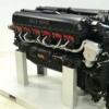
I haven't had much time for modelling lately, but since the last update I've painted and assembled the undercarriage, props and spinners. Need to touch up a few bits here and there and then add the bombs and final details. I must say I've been enjoying this build. The kit offers tremendous detail for the price. It's a little over-engineered in places, but it goes together ok in the end. I wonder if there are any other all-black Luftwaffe aircraft I could build to go with this one? I've got decals for a black Bf 110, so the new Eduard kit could be joining this one on the shelf when it arrives1 point
-
Thanks for the positive comments guys, they're most appreciated. I realise this is going to be a long project, however it will keep me out of trouble! Hopefully these will upload successfully!1 point
-
As promised, pics of the model with the canopies fitted. Everything seems to fit well enough and the Eduard masks were a godsend! I've got a couple of bits of filling and sanding to do but nothing major, and then it'll be time for paint - whoop whoop! ... Actually, no it won't - I've just remembered I've got the Eduard external panels to fit, and there are about fifty of them!1 point
-
It had to match the Eduard pre-painted etch, which is pretty dark. I used Tamiya German Grey. Here's some more progress. Most of the airframe is together now, and some of the exterior etch set is in place. Tonight I've been fitting the clear parts. A bit fiddly in places, but they all fit pretty well. Thanks to the Eduard pre-cut masks, it should look nice once painted and they saved me several evenings work to boot1 point
-
Progress - some annual leave means an opportunity to recharge the batteries and get some modelling done The forward fuselage is a seperate assembly to the rear fuselage, presumably to give Revell future options on other Ju 88 or Ju 188 variants. All this means that although the kit is beautifully detailed, it is a complex beast to put together. Some dry fitting and a little sanding was required in order to ensure there weren't any significant gaps. Of course some of these joins will form panel lines eventually, so some joins a more crucial than others! Anyways, it's all together now and it looks ok to me. I must remember to paint the seat headrests before I fix the canopies in place. I've also assembled the rest of the fuselage, including the tail wheel assembly which must be fitted before the fuselage haves can be joined. I haven't completed this bit though, just in case I damage it during construction (highly likely). I didn't have any problems with the horizontal or vertical stabilisors - they were child's play to fit. Ditto the wings. I'll probably move onto the engines next, and then dunk the transparent parts in Klear ready for masking. I'm already thanking my lucky stars that I've got the Eduard masks! After that I might get all the fiddly bits like undercarriage and props out of the way before the painting begins. With any luck, I might get this finished within the week1 point
-
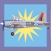
T-2E is an export version for Greece. 40 built. It is a US built, twin-engine training aircraft. T-2 is the only training jet aircraft of the Hellenic Air Force and is used for the final stage of young pilots' training. T-2s operate from Kalamata Air Force Base (120 Air Training Wing) and belong to 362 squadron "Nestor" and 363 squadron "Danaos". The specific airplane has trained many generations of Greek pilots but despite its reliability it is expected to be replaced shortly by a new training jet. Special Hobby kit OOB with Two Bobs Greek decals. After T-33 and F-84F this is my third model in Greek markings.1 point
-
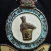
Large Rectangular 2 Tier Paint Jar Stand Progressive Engineering At this years Southern Expo held at Hornchurch on the 19th and 20th of March there was a new trader present with quite an interesting and more importantly useful range of products for the average modeller. Progressive Engineering Link had on show a number of different sized, laser cut, self assembly, MDF stands to hold modelling paint jars, pots and bottles. What caught my eye was the simplicity, practicality and elegance of the designs as it has always been a struggle to keep my paints both easy to find, organised, ready to hand and most importantly tidy on my workbench. On speaking to one of the owners Jon Page (Fraser Hale is the other owner), he explained that the products came about through the figure painting fraternity and his own experience (Jon paints model figures himself) and Hornchurch was their first show to try for a larger audience. Impressed with the product I duly handed over the cash to buy two of the 81 jar capacity Large Rectangular 2 Tier Paint Stand, only to find that with my paint of choice (Gunze Sangyo), the jars would not fit in the holes!! The normal stands were designed for Vallejo or Lifecolor which as you would expect are very popular with figure painters. Jon was not fazed by this and explained that it would be a very simple process to upscale the design into the computer controlled laser cutter to fit the Gunze Jars at no extra cost (always a pleasure to hear!). I also asked if it was possible to add a couple of extra holes to hold paint brushes and this was also confirmed as easy enough to do by Jon. So handing over a Gunze Sangyo jar as a sample I left it with him. The cost per stand was £35 including postage which is about the price of a far eastern 1/48 kit these days. One week later two packages hit my desk in Germany (an exceptionally quick turnaround service!). Inside each was a complete set of stands with one containing my returned Gunze jar. Assembly took less than 10 minutes with the included allen key in the nuts and bolts bag, so letting the pictures do the rest of the talking: Note the highlighted extra holes added on request for holding paint brushes. A further surprise on taking the stands out of the packaging was that either Jon or Fraser had twigged from my postal address that I'm a serving Sapper and laser cut into the wood was my Corps' Cap Badge. This will be remounted back into the stand and glued firmly into place. 11/10 for attention to detail and customer service there Gents! I'm pretty impressed with this product and the others in their range. The customer service and can do attitude of Progressive Engineering was also a very pleasant experience. Progressive Engineering have an ebay shop (link is on their webpage), you can also order direct from them and I would recommend this if you want to specify any changes such as brush holders or size of paint bottle/jar. Prgogressive Engineering Solutions Ltd Highly recommended. Review Sample courtesy of my wallet.1 point
-
Almost done. Only few details to finish the job.1 point
-
With the most of the decals1 point
-
I forgot to paint the black stripes along the fuselage... Now we are ready for the rest of the decals.1 point
-
The day-glo is on. I need to retouch the paint in some places and paint the yellow bands on the tail. I saw a black and white photo from the "T-83" just after the war and it had not one but two yellow bands!1 point
-
The puttying and sanding is killing me. And is not over yet. Meanwhile the propellers are done.1 point
-
the halves glued.1 point
-
The cockpit almost done. Cliff, like you said the windscreens are the worst of this kit.1 point
-
The cockpit is done. The propellers have a wrong disposition.1 point
-
A little of putty on the engines. I start gluing the windows.1 point
-
The seats and the belts are going to. I did sand this two holes that only exist and the left side of the fuselage. The cargo floor is done1 point
-
Hello The Twin Otter is going.1 point
-
Early developments: I made the gap between the cockpit and cabin load. Open the air inlets of the engines.1 point
-
Phenomenal work! I just wish that I knew how to do the salt technique, if anyone is willing to help me out on that one I would much appreciate it! And the sprayed on roundels are stunning too, the same goes for that, if anyone wants to help my brain get around the best way of spraying details like that (ie masking techniques) it would be much appreciated! I have a lot to learn!1 point


This leaderboard is set to London/GMT+01:00